PLC Simulator

Photo-Fork Sensor (Slot Sensor)

All sensor labs
Discrete inputintermediate lab

Photo-Fork Sensor (Slot Sensor)

A U-shaped optical sensor with emitter and receiver built into opposite tines — detects objects passing through the gap.

PLC address%I0.5
SignalGap interrupted
BenchLive + faults
FIELD DEVICE / 24 VDC

01 / Recognize it

What this sensor looks like

Learn the housing, active face, mounting, and connector before you meet it on a machine.

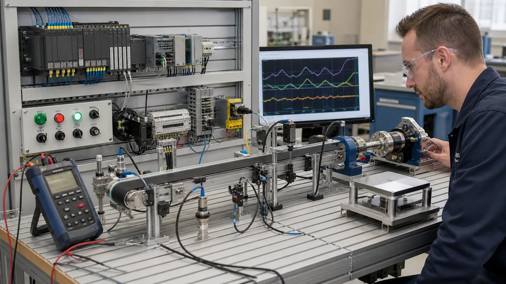
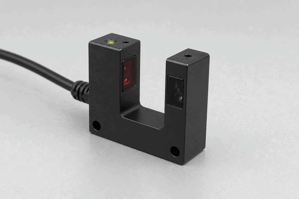
Representative real-world Photo-Fork Sensor (Slot Sensor) hardware on an industrial workbench
Representative field appearance · form factors vary by manufacturer

Hardware recognition

Know what to look for

Use the silhouette, active face, and connection style to identify the device before checking its part number and datasheet.

Body and mounting
A U-shaped housing leaves a narrow slot for a label, web, or small part.
Active face
The emitter and receiver oppose one another across the fork gap.
Cable and terminals
The cable normally exits the solid base of the fork.
Field rule: identify by appearance, then verify the exact wiring, range, approvals, and output type from the device label and datasheet.

02 / Understand the principle

Watch cause become a PLC signal

Follow the physical event through the sensing element and into the exact controller value.

Signal story / live loop

Photo-Fork Sensor (Slot Sensor): cause to controller

Paused

Now showingPhysical event

Label edge enters the fork → Receiver changes state → %I0.5 = 1

03 / Test and commission it

Commission it on the bench

Move the process, adjust the setpoint, invert the logic and inject faults. Watch the PLC value respond immediately.

Commissioning bench

Photo-Fork Sensor (Slot Sensor)

24 VDC%I0.5
OFF
35 %
48 %

PLC channel

%I0.5

RAW 0

Engineering value

35 %

Gap interrupted

Output logic
Inject a field fault

Channel healthy

Signal is inside the expected operating range

Terminals
Brown +24 VBlue 0 VBlack OUT

Commissioning note: Teach the backing and label separately when contrast is low.

Field guide

A photo-fork sensor — also called a slot sensor or fork sensor — is a self-contained through-beam sensor shaped like the letter U. The emitter sits in one tine and the receiver sits in the opposite tine, with a precisely defined gap between them. Any object passing through the slot interrupts the beam, switching the output.

Because the emitter and receiver are mechanically fixed relative to each other, there is no alignment step during installation. This makes photo-forks extremely repeatable and reliable in high-speed applications where positional accuracy matters.

The slot width is fixed at manufacture — typically 3 mm to 30 mm depending on the model. Choosing the right slot width is critical: too wide and thin objects may pass without reliable detection; too narrow and thicker parts will jam.

Photo-forks are the sensor of choice for label-gap detection on liner-less and liner-backed webs, for encoder disc reading (the slots or slots-and-teeth trigger the sensor to produce a pulse train), and for edge detection on thin films.

Electrically they follow the same NPN/PNP, NO/NC conventions as other discrete sensors. Most photo-forks output a clean square wave at high speed — models rated for 50 kHz switching are common for encoder applications.

Use this when…

  • Detecting individual sheets, labels, or thin film in a gap
  • Counting encoder disc slots for position feedback
  • Detecting the presence of a circuit board or thin part

Where you will see it

Label applicator

Photo-forks detect label gaps on a backing liner, timing the applicator head to peel and place each label precisely.

PCB handling

Slot sensors detect the leading edge of circuit boards entering a solder wave machine, starting the conveyor-speed synchronisation.

Next skill

Connect it to PLC logic

Unlock PLC integration challenges

See plans