Motion and state
Its state is used to practise permissive and trip reasoning; it is not a safety-rated engineering model.
controls · safety model
A safety relay monitors safety devices such as an emergency stop or guard switch and removes hazardous-motion permission through redundant, force-guided outputs. A standard PLC can display status and coordinate normal production, but it must not silently replace the safety function. The important PLC boundary is command versus permission: the controller may request motion only while the independently validated safety circuit reports healthy.
Create a free account to run this scenario, or try a PLC lab now — no signup.
Explore Safety relay in 3D
Load the interactive model when you are ready to rotate, inspect and operate it. Deferring WebGL keeps the reference page fast.
Its state is used to practise permissive and trip reasoning; it is not a safety-rated engineering model.
Commission it by proving active feedback before accepting enable.
Inject stuck-on, stuck-off states and require the PLC sequence to detect, stop and recover deliberately.
PLC integration guide
Dual input channels allow the relay to detect a single open circuit, contact fault or channel discrepancy. Its output contacts drive safety contactors, safe drive inputs or another validated final element according to the risk assessment. A standard PLC status bit is useful for messages and sequence inhibition, but software, network communications and an ordinary output do not acquire a safety rating because the logic looks redundant.
A manual monitored reset should be accepted only after input channels are healthy, external devices have returned to their expected state and the reset signal makes the required transition. Resetting the relay restores permission; a separate deliberate machine start command should be required. PLC logic should clear stale run requests when safety permission drops so motion cannot resume unexpectedly when the circuit is restored.
External device monitoring reads mechanically linked normally-closed auxiliary contacts from the final contactors. Before reset, those contacts must prove the contactors actually opened. If a power pole or mechanism remains closed, the feedback path prevents reset. The PLC can present a specific EDM fault to maintenance, but the safety relay performs the safety-rated monitoring.
The reference above focuses on PLC integration. The interactive school lesson shows the device, signal or mechanism before you write the control sequence.
Learn the E-stop mechanism and reset principleSignal map
PLC output Enable; PLC input Active feedback
| Signal | PLC direction | Type / range |
|---|---|---|
| Enable enable | output | bool |
| Active feedback active | input | bool |
Field checklist
Fault finding
| Symptom | Check |
|---|---|
| Safety relay will not reset | Check both input channels, reset-edge requirements, feedback-loop state, supply voltage and the device diagnostic code. |
| Relay resets but PLC still shows safety open | Trace the auxiliary status contact, input common, PLC address and any inversion in the standard program. |
| Intermittent channel discrepancy | Inspect simultaneous contact operation, cable damage, loose terminals and test-pulse compatibility. Do not mask it with PLC delay. |
Fault and recovery exercise
Inject stuck-on, stuck-off states and require the PLC sequence to detect, stop and recover deliberately.
Training model only. It does not perform a machinery risk assessment, calculate performance level or SIL, replace a safety PLC, or validate a real safety function.
Plain-English answers
Not for a safety-rated function. Use certified safety hardware and a validated design appropriate to the risk. A standard PLC may consume diagnostic status only.
The architecture can detect certain single faults and disagreement instead of allowing one hidden wiring or contact failure to defeat the stop request.
The safety device checks that reset occurs as a deliberate signal transition under valid conditions rather than accepting a permanently bridged reset input.
Free first success
Open a related browser scenario, run the PLC logic and see the component state respond. Start without installing software or entering a card.
Keep building
controls
Its visible state changes with simulated I/O, making status and diagnosis readable in the scene.
controls
Its visible state changes with simulated I/O, making status and diagnosis readable in the scene.
controls
Its visible state changes with simulated I/O, making status and diagnosis readable in the scene.
Technical reference and worked-example guide
Direct answer
The reader can trace a basic safety-relay function and explain why diagnostic status or standard PLC logic does not independently prove risk reduction.
Written for automation learners and maintenance technicians studying dual-channel emergency-stop or guard circuits, monitored reset, contactor feedback and diagnostic evidence.
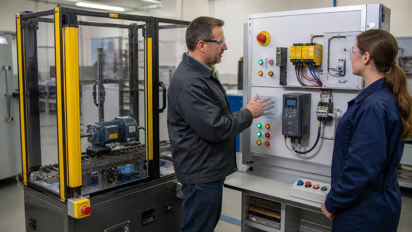
Hazard and required function, safe state, input devices, channel structure, discrepancy, reset type, output contacts, external-device monitoring, fault exclusions and diagnostic interface.
Hazardous demand through input channels, safety-relay logic, force-guided outputs, final switching devices, energy removal, stop result and reset prerequisites.
The declared protective device removes the permitted hazardous action and deliberate reset cannot initiate unexpected movement.
Cross fault, welded contactor, channel disagreement, reset held, guard cycling, supply loss, diagnostic-wire fault, restart and maintenance bypass.
A hazard, input, channel, reset, relay, output, final-device, feedback, stopping, calculation or validation mismatch.
The function designed and validated by qualified personnel on target components under the applicable risk-reduction standard and test plan.
It evaluates compatible safety inputs and controls safety-related outputs with defined fault response, diagnostics and reset behavior.
Not by default. The required safety function and performance determine the suitable architecture, components and validation process.