What you'll learn
Integrate a dual-channel guard switch, safety relay and VFD Safe Torque Off inputs. Add the ordinary run command and hardwired running/fault feedback to a PLC. STO removes motor-producing torque; it does not isolate the drive’s mains or DC bus.
Lab time: ~25 minutes.
Lesson briefing
VFD Safe Torque Off and Status Feedback
Integrate a dual-channel guard switch, safety relay and VFD Safe Torque Off inputs. Add the ordinary run command and hardwired running/fault feedback to a PLC. STO removes motor-producing torque; it does not isolate the drive’s mains or DC bus.
The device in the real world
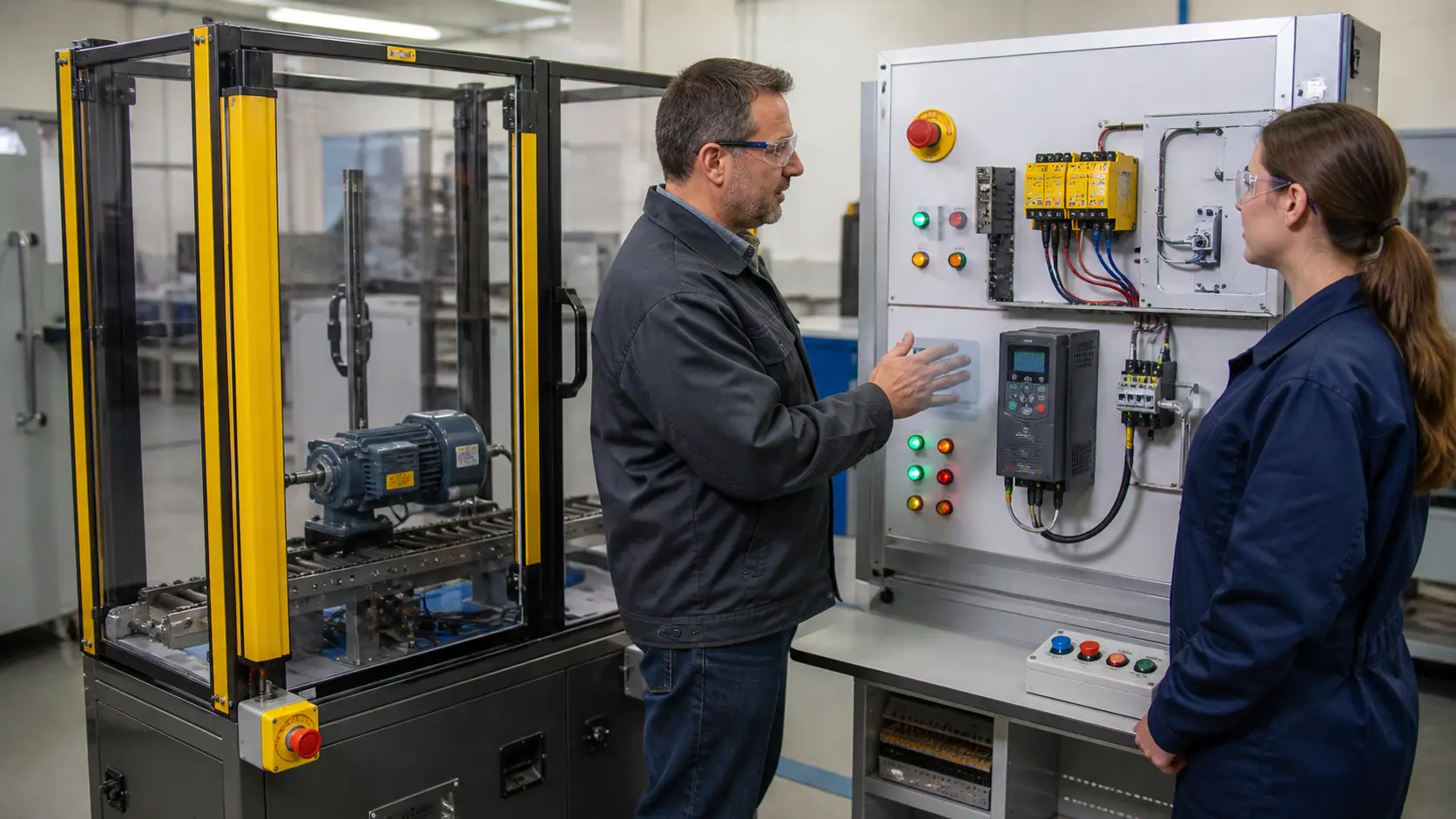
Safe Torque Off is a drive feature that stops the drive from producing torque, so the motor cannot start accidentally while a guard is open. It uses two separate input channels, STO1 and STO2, normally fed from the contacts of a safety relay. The ordinary run command from the PLC is a separate, non-safety signal. The drive also reports its running and fault status back to the PLC through simple outputs.
Why it is wired this way
Both STO channels must be independently controlled and monitored. The normal run command cannot be part of the safety function. Maintenance still requires lockable mains isolation, waiting the DC bus discharge time stated in the drive manual, and proof of dead.
Worked example
With the guard door closed, both guard channels feed the safety relay, which closes its two output poles and supplies 24 V to STO1 and STO2. The PLC can now send a run command on STF, and the drive reports RUN to input X0. Open the door and both poles drop together, torque stops and the drive shows STO active. Note that the mains and DC bus are still live inside the drive, so maintenance still needs isolation. Wire this lab by building the power path first, then the safety chain, then the PLC signals.
Common mistakes
- Feeding both STO inputs from one relay pole, which loses the independent second channel.
- Treating the run command as part of the safety function.
- Assuming STO makes the drive safe to open, when the mains and DC bus remain energised.
- Connecting the status outputs to the wrong common.
What you can now do
You can wire an STO chain from a guard switch through a safety relay to the drive, and keep the run command and status signals separate from it.
Commissioning standard
Verify each STO channel on its own, then both together, and prove that the motor cannot turn with either channel open.
Training material. Follow your site procedures, local electrical code and the manufacturer's instructions. Lockout/tagout and a qualified person are required for real equipment.
Hints
Wire the guard switch OSSD channels to separate safety relay inputs.
Sign up to unlock the full hint sequence.
Sign up to unlock the full hint sequence.
This lesson uses 9 placed components on the lab canvas. Components are vendor-neutral (no proprietary trademarks); the wiring rules apply to any equivalent industrial part.
Sign up to preview
Create a free account to preview this Pro lab; upgrade to open the interactive circuit.
Sign up to preview →