
RSLogix 500 and 5000 addressing guide
RSLogix simulator: data-file addresses, Logix tags and emulator options
Direct answer
Most RSLogix simulator searches come from learners who need ladder practice without a Rockwell license, a Windows PC or a controller. First decide whether the target is RSLogix 500, with SLC-style data files such as B3, N7, T4 and C5, or Studio 5000 with named tags. Then practice the transferable rung logic and confirm every address in the official tool.
This guide is written for students, electricians and maintenance technicians who have inherited MicroLogix or SLC 500 programs, or who are heading toward ControlLogix and CompactLogix work, but cannot yet run Rockwell software on their own machine. The intended result is specific: the learner can decode a legacy address such as B3:2/5 or T4:1/DN, describe the equivalent Logix tag, and build and test the same start-stop, timer and counter behavior in the browser before recreating it in the correct Rockwell package.
Two software generations
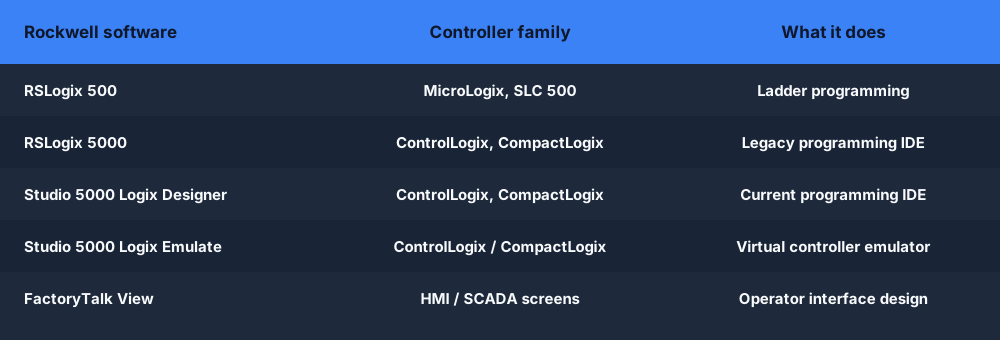
RSLogix 500 programs MicroLogix and SLC 500 controllers and organizes memory as numbered data files. RSLogix 5000, now Studio 5000 Logix Designer, programs ControlLogix and CompactLogix with named tags, tasks, programs and routines. The rung mnemonics look alike, but each project belongs to one generation, and moving between them is a conversion job rather than simply opening a file.
Default data files
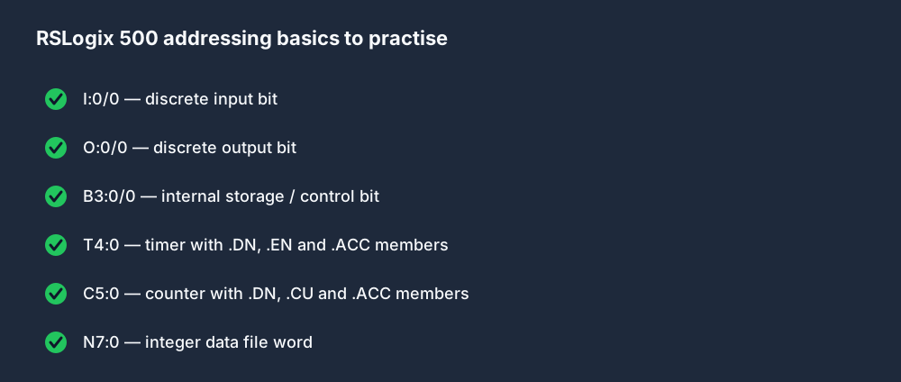
An SLC-style project starts with reserved files: O0 outputs, I1 inputs, S2 status, B3 bits, T4 timers, C5 counters, R6 control structures and N7 integers, with F8 floating point on controllers that support it. Programmers add further files such as N10 or B11. The letter fixes the data type; the number only says which file holds the data.
Decoding an address
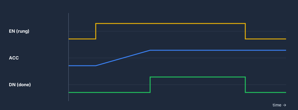
Read an address as file type, file number, element, then a slash for a bit or a dot for a word member. B3:2/5 is bit 5 of word 2 in bit file 3, and B3/37 names the same bit by continuous numbering. N7:10 is integer element 10. T4:1/DN is the done bit of timer 1, while T4:1.ACC is its accumulator word.
Physical I/O notation
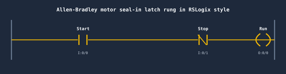
In SLC-style addressing, I:1/3 means input image, slot 1, bit 3, and O:2/0 means output slot 2, bit 0; MicroLogix embedded I/O sits in slot 0. Logix replaces rack positions with module-defined tags such as Local:1:I.Data.3, normally reached through an alias tag with a descriptive name, so the rung reads a meaning rather than a slot.
Timer time base
An SLC-style timer stores preset and accumulator as integer counts of a selected time base, commonly 0.01 s or 1.0 s, so a preset of 500 may mean 5 seconds or more than 8 minutes. Logix TIMER tags count milliseconds. Copying the raw number across without converting it is a classic migration mistake and produces delays that are wrong by a factor of 100 or 1000.
Emulator or learning simulator
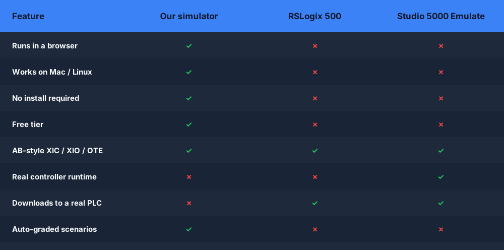
RSLogix Emulate 500 and Studio 5000 Logix Emulate are Windows soft controllers that execute a real project and accept online connections from the programming software. RSLogix Micro Starter Lite is a free programming edition for selected small MicroLogix controllers, not an emulator. A browser learning simulator sits one step earlier: it shows rung behavior without any of that toolchain.
- 01
Identify the generation
Read the controller family and project file type from the documentation: MicroLogix or SLC 500 with an .RSS file means RSLogix 500, while ControlLogix or CompactLogix with an .ACD file means Studio 5000.
Evidence: A written note of controller family, software generation and addressing model before any practice begins.
Avoid: Following a Studio 5000 tutorial to maintain an SLC 500 program, or the other way round.
- 02
Build an address map
List each field device from the drawing with its legacy address and a descriptive name, for example I:1/0 START_PB, O:2/0 MOTOR_M1 and B3:0/1 CONVEYOR_RUN_REQ.
Evidence: Every bit, timer and counter the rung uses has one owner, one meaning and one address on the map.
Avoid: Inferring what a bit does from its address alone when the symbol and description are available.
- 03
Recreate the rung with named tags
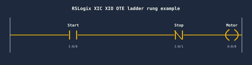
In the browser Allen-Bradley dialect, declare TAG entries for the inputs and outputs, bind them to I:slot/bit and O:slot/bit addresses, and write the XIC, XIO and OTE rung.
Evidence: The program compiles and the live rung highlight follows each simulated input you toggle.
Avoid: Assuming the browser dialect models the full SLC data table and typing T4 or C5 file references into it.
- 04
Convert timer presets
Take the legacy preset and its time base, calculate the real duration, and enter it in milliseconds on the browser timer instance while noting the value a Logix TIMER tag would need.
Evidence: The observed delay matches the calculated duration rather than the raw legacy number.
Avoid: Copying a preset of 500 from a 0.01 s timer straight into a millisecond timer.
- 05
Test transitions and restart
Exercise start, stop, stop pressed during start, an interrupted timer and a counter reset from a clean state, then repeat the cases with the output already on.
Evidence: Each case gives the same result on repeated runs and matches the prediction written beforehand.
Avoid: Accepting one successful start as proof that the program is correct.
- 06
Move to the official tool
Rebuild the checked logic in the correct Rockwell software, with Emulate or a training controller if one is available, and verify addresses, presets, one-shots and status bits there.
Evidence: A monitored run in the target environment plus a list of any behavior that differed from the browser.
Avoid: Treating a browser pass as proof that a MicroLogix, SLC or Logix controller will behave the same way.
| Observed symptom | Inspect | Interpretation | Next proving action |
|---|---|---|---|
| Timer finishes far too early or far too late | Legacy time base, preset value, accumulator and the unit assumed after translation | An error of roughly 100 or 1000 times points to a time-base or millisecond conversion, not to faulty rung logic. | Recalculate the duration as preset multiplied by time base and re-enter the preset in the correct unit. |
| Output stays off although its rung is true | Every OTE, OTL and OTU that writes the same address or tag, and where each sits in the scan | A later rung writing the same bit false overrides the earlier true result before outputs are updated. | Cross-reference the address, keep a single owner for each output and retest. |
| Panel input changes but the contact never does | Slot number, bit number, the spelling of the I:slot/bit address and the tag it is bound to | An address that points at the wrong slot or bit reads a different field point entirely. | Compare drawing, address map and tag declaration, then toggle only the intended input. |
| Counter sits at its preset permanently | Counter done bit, accumulated count, the reset instruction and the condition that drives it | A counter keeps its count until an explicit reset clears it; reaching the preset does not clear anything. | Add or repair the reset path and test a second batch from a clean state. |
| Converted program behaves differently in Logix | Preset units, one-shot operands, integer sizes, indirect or indexed addresses and any S2 status-file references | SLC status bits and indirect addressing have no one-to-one Logix equivalent; Logix reads controller status through GSV instructions instead. | List every S2 reference and indirect address, design an explicit Logix replacement and test each one. |
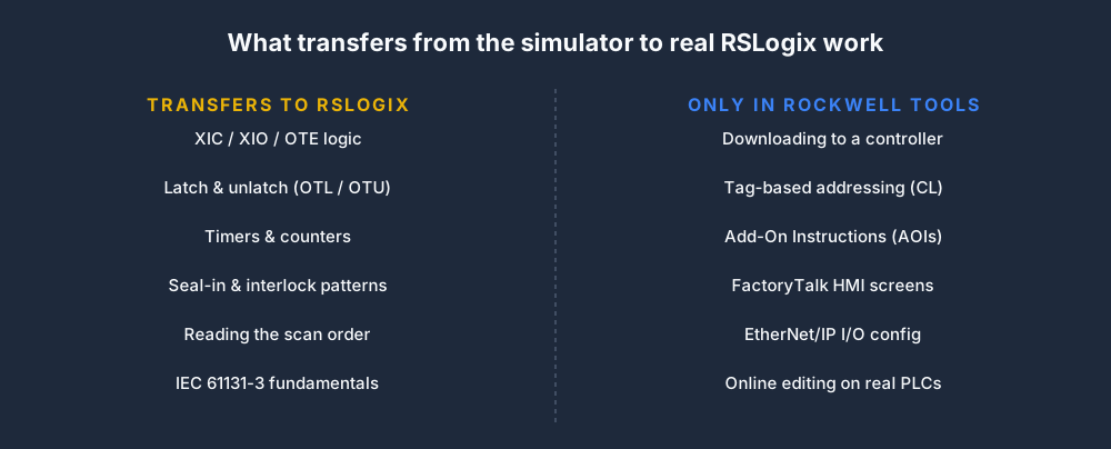
| Every free RSLogix simulator turns out to need an install | Operating system, license availability, target controller and what actually has to be proven | Official emulators are Windows products tied to the Rockwell toolchain; learning rung behavior does not require them, but going online does. | Practice the transferable logic in the browser now and budget time on Emulate or a training controller for target proof. |
Product evidence / 05
What the browser practice can actually demonstrate
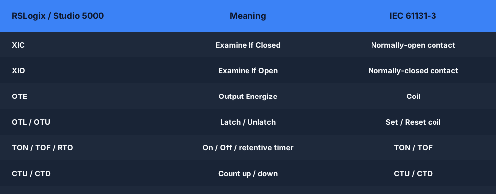
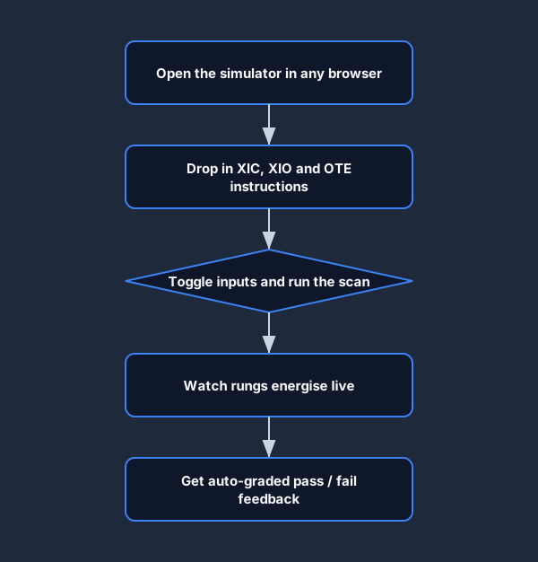
The browser Allen-Bradley dialect accepts XIC, XIO, OTE, OTL and OTU rungs, TAG declarations bound to I:slot/bit and O:slot/bit style addresses, and named timer and counter instances. Programs run on a read-inputs, solve-rungs, write-outputs scan against a machine model, and scenarios are auto-graded on observed behavior.
What do B3, N7, T4 and C5 mean in RSLogix 500?
They are default data files in SLC 500 and MicroLogix projects. B3 holds bits, N7 holds 16-bit integers, T4 holds timer structures and C5 holds counter structures. The letter defines the data type and the number identifies the file, so a programmer can add more files, such as N10 or T12, when a project needs them.
How is a timer done bit addressed in RSLogix 500 compared with Studio 5000?
RSLogix 500 addresses the done bit of timer 0 in file 4 as T4:0/DN, while the preset and accumulator words are T4:0.PRE and T4:0.ACC. In Studio 5000 you create a TIMER tag with a name such as Fill_Delay and read Fill_Delay.DN. The member names match, but the Logix preset is counted in milliseconds.
Is RSLogix Micro Starter Lite a simulator?
No. It is a free, limited programming edition in the RSLogix 500 family for selected small MicroLogix controllers. You can write and edit ladder with it, but the logic only executes in a connected controller or a separate emulator product. That gap is why learners without hardware go looking for a simulator that shows rungs actually running.
Can RSLogix Emulate 500 run on a Mac?
Not natively. RSLogix Emulate 500 and Studio 5000 Logix Emulate are Windows applications that work alongside Rockwell programming and communication software, so a Mac user normally needs a Windows virtual machine and the relevant licenses. A browser simulator avoids that setup for rung practice, but it does not replace an emulator for online testing of a real project.
Can Studio 5000 open an RSLogix 500 program?
Not directly. An SLC or MicroLogix project has to be converted, and file-based addresses become tags and arrays with translated names that need manual review. Treat any converted program as a draft: recheck timer presets, one-shots, indirect addressing and every S2 status reference before it is trusted on a controller.
Should I learn RSLogix 500 or Studio 5000 first?
Learn the one used on the equipment you will maintain or the role you are targeting. Many plants still run SLC and MicroLogix controllers, while new Rockwell projects generally use Logix controllers. Rung logic transfers in both directions; the addressing model, project structure and software workflow are what you relearn when you switch.
How does the browser simulator handle Allen-Bradley addresses?
The browser Allen-Bradley dialect binds named tags to I:slot/bit and O:slot/bit style inputs and outputs and uses named timer and counter instances with millisecond presets. It is a learning subset rather than an SLC data table, so use it to practice the logic and translate B3, N7, T4 and C5 references into named tags as you go.
What should I check before applying this to a real SLC or Logix controller?
Confirm the controller family, firmware and software version, every address or tag, timer time bases, one-shot operands, retentive behavior at power-up and any first-scan logic. Then monitor the program in the official tool with Emulate or a training controller, and follow site change-control rules before editing any production program.