
PLC Simulator
Allen-Bradley dialect

Allen-Bradley PLC Simulator Online

Practise recognizable Allen-Bradley-style ladder vocabulary in your browser. Build XIC/XIO contacts, OTE/OTL/OTU coils, timers and counters, then prove the control pattern against machine I/O and repeatable tests. No install for the guided first program.

Join 13100+ learners practicing PLC programming

Allen-Bradley PLC simulator — practice RSLogix-style ladder logic with XIC, XIO, OTE, TON and CTU in the browser
Practice Allen-Bradley RSLogix-style ladder logic in the browser — no Studio 5000 license required.
Real allen bradley plc simulator footage

See this exact skill in the working simulator.

Watch the real browser product respond to the task on this page, then try the same practical workflow yourself. No slides, concept mockups, install, or credit card.

Try this in the browser
Allen-Bradley PLC Simulator — Practice Studio 5000-Style Logic Online

Allen-Bradley-style logic in context

Move from instruction names to observable machine behavior.

These simulator-specific views connect tag-based logic to I/O, motor control, timing, counting and fault tracing. They are learning contexts—not depictions of a proprietary Rockwell IDE or controller runtime.

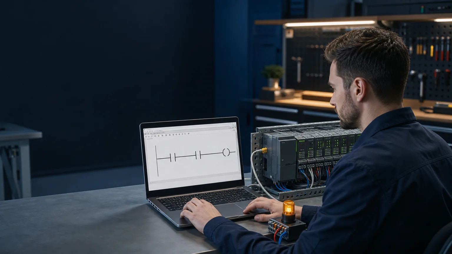
Controls technician using an Allen-Bradley-style browser ladder simulator beside a generic modular PLC I O training rack
01The browser exercise connects a rung to observable I/O without pretending to be a native controller engineering workstation.
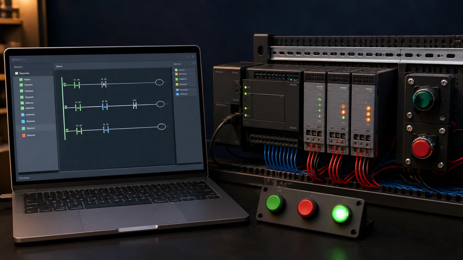
Generic PLC I O trainer with start stop buttons status LEDs and a browser ladder editor for tag-based control practice
02Readable tag names help learners trace a signal from pushbutton to input state, instruction truth and output response.
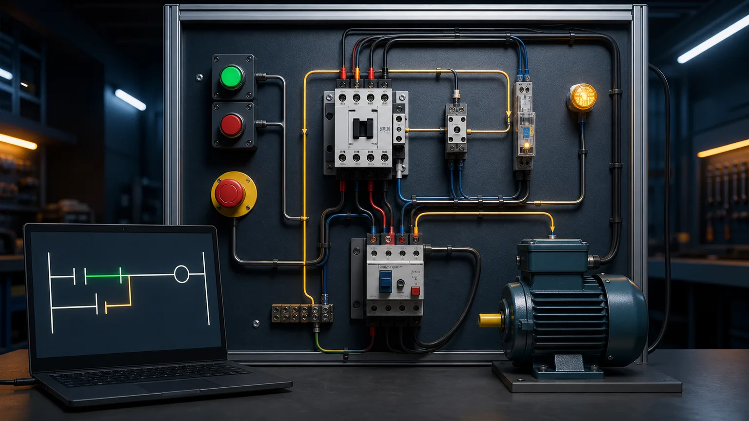
Guarded motor starter training panel with contactor overload start stop controls and an Allen-Bradley-style seal-in rung
03A seal-in exercise gives XIC, XIO and OTE a practical purpose: start, hold, stop and protect a motor command.
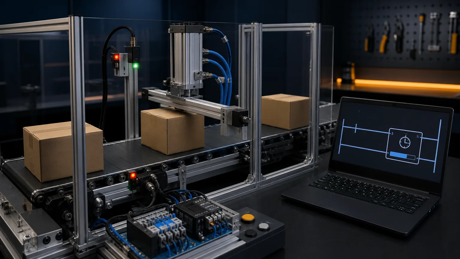
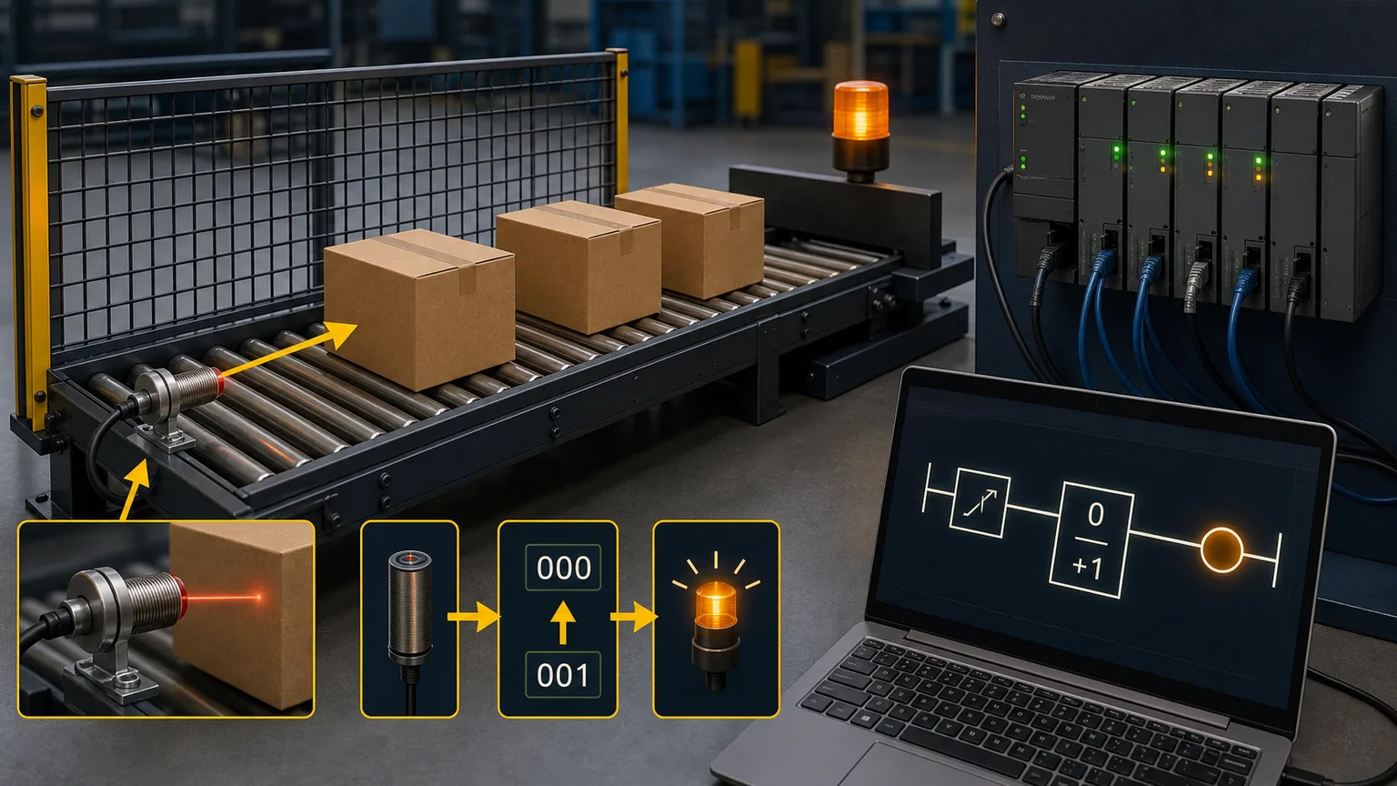
Guarded conveyor training cell using a photoelectric sensor and browser PLC timer block to control a pneumatic stop gate
04A timed conveyor makes rung state visible through sensor detection, elapsed time and a repeatable actuator response.
Pallet and carton conveyor exercise with sensor PLC input modules and a browser count-up ladder block
05Counter practice is anchored to a real event: one sensor edge per part, a changing accumulated value and an output at the target count.
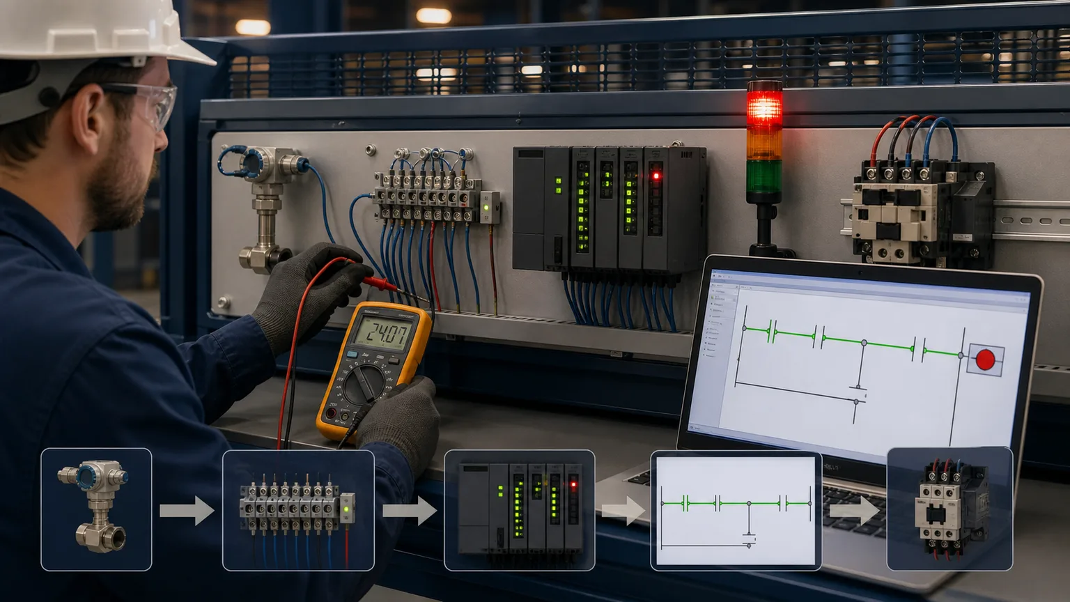
Technician tracing a 24 volt field signal through terminals PLC input LEDs live ladder continuity and an output contactor
06The troubleshooting path stays evidence-based: field device, terminal, input channel, tag, rung, output channel and actuator.

Why AB programmers use this

Familiar instruction vocabulary. Observable execution. No install.

RSLogix-style instructions

Practice common learning mnemonics such as XIC, XIO, OTE, OTL, OTU, TON, TOF and CTU, while keeping the boundary between transferable concepts and a proprietary runtime explicit.

Tag-based addressing

Use readable names such as MotorRun and inspect timer or counter state in context. The lesson model builds tag fluency without reproducing a controller tag database.

170 source-catalogued practice records

Real machine control problems: conveyor sorting, motor sequencing, batch mixing, HVAC control. Write AB-style ladder and get immediate pass/fail feedback.

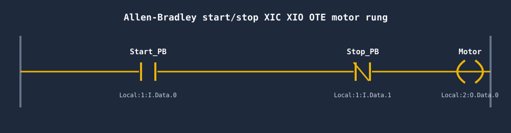
Allen-Bradley start/stop ladder rung with XIC Start, XIO Stop and OTE Motor output coil in Studio 5000 tag style
A start/stop rung in Allen-Bradley style: XIC Start, XIO Stop, OTE Motor.
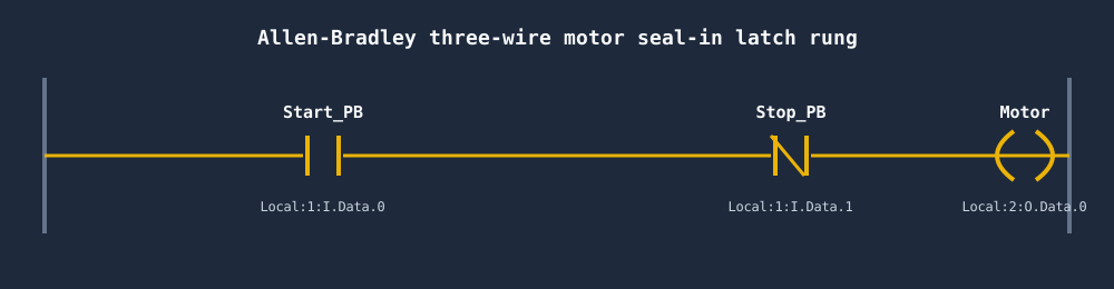
Allen-Bradley three-wire motor seal-in latch rung where the OTE Motor coil seals itself around the XIC Start contact
The classic three-wire seal-in: the Motor coil holds itself in around the Start button.

AB instruction set

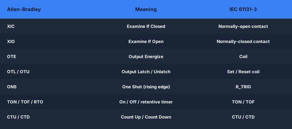
The Allen-Bradley instructions, mapped to IEC 61131-3

Common Allen-Bradley mnemonics such as XIC, XIO, OTE, OTL/OTU, TON and CTU have transferable IEC concepts, but vendor implementations are not always one-for-one. The learning tracks compare intent and behavior while keeping production validation in the target vendor environment.

Table mapping Allen-Bradley instructions XIC, XIO, OTE, OTL, OTU, TON, CTU to their IEC 61131-3 equivalents
Allen-Bradley instruction mnemonics and their IEC 61131-3 equivalents.

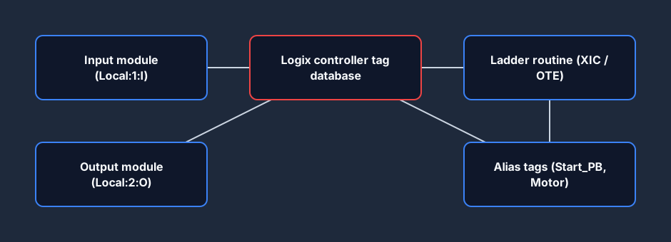
Tag-based, not file-based

ControlLogix and CompactLogix controllers address I/O through a symbolic tag database, not RSLogix 500 file addresses. Physical module data is aliased to descriptive tags your ladder routine reads directly.

ControlLogix and CompactLogix tag-based addressing model showing input and output modules mapped to controller tags and ladder routines
The Logix tag-based model: physical modules → controller tag database → ladder routine.
Allen-Bradley ControlLogix architecture learning diagram showing a CPU scanning input and output modulesA modular PLC rack on a backplane: power supply, CPU processor, input module, output module and a communications module side by side.PLC RACKbackplane busPSUPowerCPUProcessorDIInputDOOutputNETComms
A simplified learning model of the CPU-and-I/O relationship—not a ControlLogix backplane or firmware emulator.

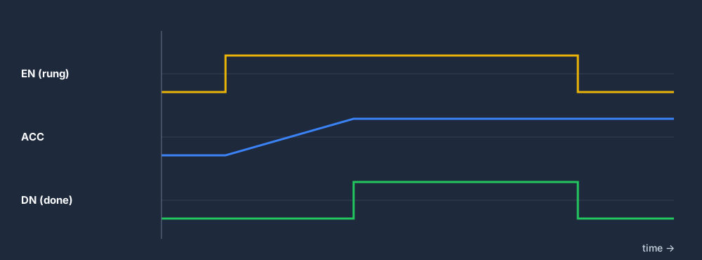
TON on-delay timer behavior

The timer lesson demonstrates the core on-delay relationship: timing begins with a true enable condition, the accumulated value advances, and the done state changes at the preset. Controller-specific status behavior still belongs in the vendor documentation and target hardware test.

Allen-Bradley TON on-delay timer timing diagram showing the EN rung, ACC accumulator ramp and DN done bit
An Allen-Bradley TON timer: DN turns on only after ACC reaches the PRE preset.

Scenarios

Practice scenarios in AB dialect

Motor Start/Stop

Seal-in rung, OTL/OTU pattern, overload interlock.

View scenario →

Conveyor Sort

Diverter gate, part counter, CTU with DN bit.

View scenario →

Batch Mixer

Multi-step sequence, TON timers, recipe steps.

View scenario →

E-Stop Reset

Safety circuit, monitored E-stop, reset handshake.

View scenario →

Jog/Run Motor

Jog vs run mode, anti-tie-down, feedback check.

View scenario →

Forward/Reverse

Contactor interlock, direction feedback, timer delay.

View scenario →

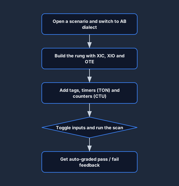
How it works

01

Prove the first loop

Open /try without an account, complete the guided rung and observe the output.

02

Choose the AB learning dialect

Use the Allen-Bradley-style vocabulary where the exercise supports it and compare the transferable control pattern.

03

Build your program

Use common contacts, coils, timers and counters, then connect each instruction to a scenario purpose.

04

Get graded

Auto-grader runs every test case. Instant pass/fail with per-test breakdown.

Flowchart for getting started practicing Allen-Bradley ladder logic — switch to AB dialect, build XIC XIO OTE rungs, add TON and CTU, run the scan, get graded
Getting started: from AB dialect to auto-graded feedback in five steps.

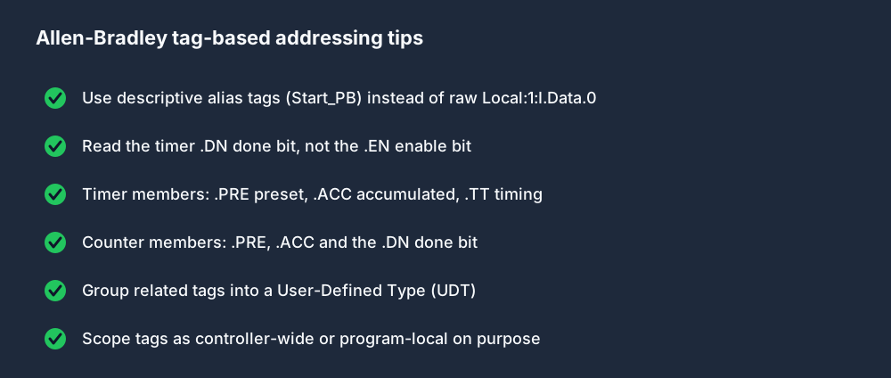
Tag-based addressing tips

Moving from file-based RSLogix 500 to Studio 5000 tag-based addressing trips up most learners. These conventions get you fluent fast.

Checklist of Allen-Bradley tag-based addressing tips — alias tags, reading the DN done bit, timer and counter members, UDTs and tag scope
Allen-Bradley tag and member conventions worth practicing early.

Ladder fundamentals

The Allen-Bradley building blocks you practise here

The most transferable AB concepts are ladder symbols, scan order, I/O state, timers, counters and evidence-based troubleshooting. The simulator drills that reasoning so common vocabulary becomes familiar before vendor-specific project work.

Allen-Bradley ladder symbols — XIC examine-if-closed contact, XIO examine-if-open contact, OTE output coil, and OTL/OTU latch coilsThe core ladder logic symbols side by side: XIC examine-if-closed, XIO examine-if-open, OTE output energize, OTL output latch and OTU output unlatch.XICIfXIOIfOTEEnergizeLOTLLatchUOTUUnlatch
The core ladder symbols mapped to AB mnemonics: XIC, XIO, OTE, and the OTL/OTU latch pair.
The Allen-Bradley Logix scan cycle — read inputs into the image table, solve the ladder routines, write the output image table, repeatThe repeating PLC scan cycle: read inputs, execute the ladder logic, update outputs, then housekeeping, looping continuously.1Read Inputs2Execute Logic3Update Outputs4HousekeepingSCANCYCLE
The Logix scan the simulator runs — input scan, program scan, output scan, every cycle.
Allen-Bradley digital I/O — field input devices and output loads mapped to controller tags in the Logix input and output image tablesA digital input pushbutton wired to a PLC input card, and a PLC output card driving a lamp, with a sinking versus sourcing hint.I/O CARDINPUTOUTPUTPushbuttonI:0/0LampO:0/0sinking (NPN) vs sourcing (PNP)
Digital I/O mapped to Logix tags — buttons and sensors in, contactors and lamps out.
An Allen-Bradley CTU count-up counter — the CU bit pulses, ACC increments, and the DN done bit sets when ACC reaches PREA CTU count-up counter: each input pulse increments the accumulator toward the preset, and the done (DN) bit turns on when count reaches preset.count pulsesCTUPRE 5ACC 3ACCcount toward presetDNdone bit
An AB CTU counter — ACC increments on each CU pulse and DN sets at PRE.
Allen-Bradley PLC troubleshooting flow — verify power flow on the rung, check input forcing, confirm the OTE coil energises, then trace the scan in Studio 5000 online modeA PLC fault-diagnosis flow from top to bottom: observe the symptom, check the inputs, check the logic, check the outputs, then apply the fix.SymptomCheck inputsCheck logicCheck outputsFix
The troubleshooting reasoning transfers to online monitoring: prove each link in the signal path before changing the program.
A browser Allen-Bradley PLC simulator running a ladder rung online with no Studio 5000 install — practice XIC, XIO and OTE instructions instantly on any deviceA web browser window running a PLC ladder logic simulator with an input/output strip, requiring no installation or download.plcsimulator.app/playno installINPUTSOUTPUTS
The online AB simulator: a ladder rung running in a browser tab — no Studio 5000 license, any OS.

Where browser practice fits beside vendor tools

Start the first guided program in a browser without installing a vendor engineering environment
Practice on common desktop operating systems before arranging supervised hardware access
Use repeatable scenario tests and guided feedback to expose logic mistakes early
Compare Allen-Bradley-style vocabulary with other PLC learning dialects
Build machine-sequence and fault-tracing fluency before controller-specific commissioning
Use eligible completion evidence as portfolio support, not as a Rockwell credential
Honest scope

The browser editor covers a useful Allen-Bradley-style training subset. It does not claim to model the complete ControlLogix or CompactLogix instruction set, runtime, firmware or project workflow.

Feature / InstructionCoveredNotes
XIC / XIO learning mnemonicsCoveredNormally-open and normally-closed contact concepts in the graphical rung editor
OTE / OTL / OTU learning mnemonicsCoveredOutput, set and reset coil concepts in the graphical rung editor
TON / TOF timer blocksCoveredGeneric on-delay and off-delay behavior for scenario learning and testing
CTU / CTD counter blocksCoveredGeneric count-up and count-down blocks with observable state
Readable tag namesCoveredScenario variables and internal state, not a native controller tag database
Parallel branchesCoveredGraphical series and parallel logic for AND/OR control patterns
PID learning blockCoveredA generic training block, not instruction parity with Rockwell PIDE
Complete Logix instruction libraryNoThe training subset is intentionally narrower than Studio 5000
Studio 5000 project filesNoThe browser does not create or open native .ACD projects
Hardware download or online editingNoNo connection to a ControlLogix or CompactLogix backplane
Safety, motion and drive commissioningNoRequires approved vendor tools, hardware and site procedures

Try it free. No Studio 5000 license needed.

Complete one guided program without an account, then create a free account for 32 source-tagged catalog records. Pro adds further catalog and learning access according to current entitlements.

Questions

Allen-Bradley Simulator FAQ

It uses recognizable Allen-Bradley-style learning vocabulary for common ladder concepts, including XIC, XIO, OTE, OTL, OTU, TON and CTU. It is an independent educational dialect, not the proprietary Logix runtime, firmware, tag database, instruction library or project format. Always validate production logic in the correct Rockwell engineering environment and on the target controller.

Practice AB ladder logic today

No install. No Studio 5000 license. No credit card.

Build your first rung →

RSLogix-style ladder, timers and tags

Allen-Bradley PLC simulator: XIC/XIO rungs, OTE latches, TON timers and counters

Direct answer

An Allen-Bradley PLC simulator lets you build and run RSLogix-style ladder without a controller or a Studio 5000 license. This browser version accepts XIC, XIO, OTE, OTL and OTU with named timer and counter blocks, runs them against modeled machine I/O and grades the observed behavior. It teaches transferable logic; it is not Rockwell firmware or a Logix project emulator.

This guide is written for students, maintenance technicians and PLC programmers who will meet RSLogix 500 or Studio 5000 projects at work and want to practice reading and writing Allen-Bradley-style ladder before they have controller access. The intended result is specific: the learner can predict what each rung writes on every scan, choose deliberately between OTE and an OTL/OTU pair, use timer and counter done states correctly, and name the behaviors that still have to be confirmed on a Rockwell controller.

System map / 02

NODE 01observable

XIC and XIO examine a bit, not a device

XIC is true when its referenced bit is 1 and XIO is true when it is 0. Neither instruction knows how the field device is wired. A normally closed stop button holds its input at 1 while healthy, so the run rung examines it with XIC, which surprises learners who expect XIO to mean stop.

NODE 02observable

OTE rewrites its bit every scan

OTE copies the rung result into its bit on every scan: a true rung sets it and a false rung clears it. That makes OTE non-retentive and means the last OTE written to a tag decides its value. OTL sets a bit and OTU clears it only while their rungs are true; between those events the bit keeps its state.

NODE 03observable

Timer status members

A Logix TON carries EN, TT and DN status bits plus a preset and an accumulator counted in milliseconds. EN follows the rung, TT is true while timing, DN turns on when the accumulator reaches the preset, and a false rung resets the timer. RSLogix 500 timers use a selectable time base instead, so the same preset number can mean a different duration.

NODE 04observable

Counters count transitions

CTU adds one on each false-to-true transition of its rung, not on every scan the rung stays true; the CU bit stores the previous rung state to detect that edge. DN sets when the accumulator reaches the preset and counting continues past it until a reset clears it. CTD decrements on the same kind of transition.

NODE 05observable

Tag names versus file addresses

RSLogix 500 locates data by file type and position: I:1/0 for an input bit, B3:0/5 for an internal bit, T4:2.DN for a timer done bit, N7:10 for an integer. Logix controllers use named tags with controller or program scope, and alias tags that point at module data. The simulator TAG line joins both ideas by binding a name to a legacy-style address.

NODE 06observable

Scan order and I/O timing

Rungs are solved top to bottom, so a bit changed on rung 5 is already new when rung 9 reads it but still old when rung 2 reads it in the same scan. SLC-style controllers exchange I/O between scans; Logix controllers update I/O asynchronously at each module RPI, so an input can change mid-scan unless it is buffered. The simulator uses the synchronous read, solve, write model.

Procedure / 03

  1. 01

    Write the I/O list first

    Declare every input and output with a TAG line, a descriptive name and an address, and record whether each field contact is wired normally open or normally closed.

    Evidence: Every rung references a named tag and the normally closed stop is examined with the correct instruction.

    Avoid: Starting with rungs and inventing tag names mid-program.

  2. 02

    Build the seal-in rung

    Put XIC Start in parallel with XIC Motor, in series with the stop condition, driving OTE Motor.

    Evidence: Start holds the output through the parallel branch and stop drops it on the next scan.

    Avoid: Using OTL and OTU for a run command that must drop out when a permissive or power is lost.

  3. 03

    Add a delay with TON

    Enable a TON from the condition that must persist and drive the next action from the timer done output, not from the enable.

    Evidence: The output changes only after the preset and stays off if the condition breaks early.

    Avoid: Driving the output from the same condition that enables the timer, which makes the delay do nothing.

  4. 04

    Count real events

    Feed a CTU from a sensor that goes false between parts and give it a separate reset condition.

    Evidence: One part produces one count and the done output appears exactly at the preset.

    Avoid: Forgetting the reset, so the second batch starts with the counter already done.

  5. 05

    Trace one scan at a time

    Change inputs slowly with the live rung highlighting on and write your prediction for each rung before it evaluates.

    Evidence: The prediction matches the highlighted rung and the output state for every input change.

    Avoid: Watching only the final output lamp and guessing which rung failed.

  6. 06

    Recreate in Rockwell software

    Rebuild the proven pattern in RSLogix 500 or Studio 5000 against the real I/O configuration and test it online under site procedures.

    Evidence: The same test cases pass on the target controller, including power-up, mode change and fault recovery.

    Avoid: Assuming browser results cover prescan, first-scan, RPI timing or retentive memory behavior.

Diagnostic matrix / 04

Diagnostic symptoms, inspection points, interpretations and next actions for Allen-Bradley PLC simulator: XIC/XIO rungs, OTE latches, TON timers and counters
Observed symptomInspectInterpretationNext proving action
Output ignores a rung that is clearly trueCross-reference every OTE that writes the tag and the order of those rungsDuplicate destructive bit: two OTEs write the same bit and the lower rung overwrites the upper one on every scan.Merge the conditions into one OTE rung with parallel branches, or use an OTL/OTU pair on purpose.
Motor keeps running with start and stop both pressedRung order of the OTL and OTU instructions and the conditions on each rungWhen both rungs are true in one scan the instruction solved last decides the bit; an OTL below its OTU makes start dominant.Place the OTU after the OTL, or add the stop condition to the OTL rung so stop always wins.
TON never reaches doneThe enable condition over several seconds, the accumulator and any brief drop of the enableA TON resets its accumulator whenever its rung goes false, so a chattering sensor or a one-scan pulse restarts timing.Hold or debounce the enable; in Logix use an RTO with a RES where accumulated time must survive interruptions.
Counter increments once, then stopsThe rung feeding the CTU, the reset condition and the accumulator valueA CTU needs a new false-to-true transition for every count; a feed that stays true, or a reset held on, blocks further counts.Confirm the feed goes false between parts and the reset is false while counting.
One-shot logic fires unpredictablyThe storage bit of each ONS and whether any is shared or written by other logicONS remembers the previous rung state in its storage bit; sharing or overwriting that bit corrupts edge detection.Give every ONS a unique storage bit; in the learning dialect practice the same edge with R_TRIG or an explicit memory-bit rung.
Converted RSLogix 500 logic reacts to the wrong inputAlias tags, module slot, and the original I:slot/bit address against the Logix Local:slot:I.Data.bit pathA conversion maps file addresses to tags; an alias pointing at the wrong slot or bit gives correct logic with the wrong signal.Toggle one field input at a time and confirm exactly one expected tag changes.

Product evidence / 05

What the browser practice can actually demonstrate

The Allen-Bradley learning dialect parses XIC, XIO, OTE, OTL and OTU with series and parallel branches, TON, TOF and TP timers, CTU, CTD and CTUD counters, and R_TRIG and F_TRIG edge blocks. A TAG line binds a readable name to a legacy-style address such as I:0/0, and scenario checks pass only on observed input-to-output behavior.

Answer surface / 07

What is the difference between OTE and OTL in Allen-Bradley ladder?

OTE writes its bit true or false on every scan to match the rung, so the output drops as soon as the rung goes false. OTL only sets the bit, which then stays on until an OTU rung clears it, even if the OTL rung goes false. Use OTE for most outputs and OTL/OTU only where retained state is intended.

What is a duplicate destructive bit?

It is a bit written by more than one non-retentive output, typically two OTEs on the same tag in different rungs. Each scan the lower rung overwrites the upper one, so the upper rung appears to do nothing. Combine the conditions into a single OTE rung using parallel branches, or deliberately use a latch and unlatch pair.

What is the difference between TON, TOF and RTO?

A TON sets its done bit after its rung has been true for the preset time and resets when the rung goes false. A TOF keeps done true for the preset time after the rung goes false. An RTO accumulates time like a TON but keeps the accumulated value when the rung goes false and needs a RES to clear it.

How do I reset an Allen-Bradley counter?

In RSLogix 500 and Studio 5000 a RES instruction addressed to the counter clears its accumulator and status bits while its rung is true. In the simulator learning dialect the CTU block takes a reset input instead. In both cases keep the reset false while counting, or every new count is immediately cleared.

Why is a normally closed stop button examined with XIC?

A normally closed stop contact keeps the input energized, so the input bit is 1 while the button is released. XIC is true while that bit is 1, which lets the rung run, and pressing stop drops the bit and breaks the rung. A broken wire also stops the machine, which is why stop circuits are wired this way.

Does the simulator support ONS, OSR and RTO?

Not in the current Allen-Bradley learning dialect. It accepts TON, TOF and TP timers, CTU, CTD and CTUD counters and R_TRIG and F_TRIG edge blocks. You can practice the same ideas with those blocks or with an explicit memory-bit rung, then use the real Rockwell instructions when you move to RSLogix 500 or Studio 5000.

Can I import an RSLogix or Studio 5000 project?

No. The simulator does not open or export .ACD or .RSS files, module configurations or tag databases. Rebuild the specific rungs you want to study in the learning dialect using synthetic tag names, and do not paste proprietary plant logic into a training account. Validate any production change in the Rockwell software and on the target controller.

Does the simulator scan like a ControlLogix controller?

Only at the level of rung order. The simulator reads inputs, solves the program top to bottom and then writes outputs on a deterministic teaching clock. A ControlLogix or CompactLogix controller runs tasks with their own periods and priorities and updates I/O asynchronously at module RPIs, so timing-sensitive logic must be retested on the target.