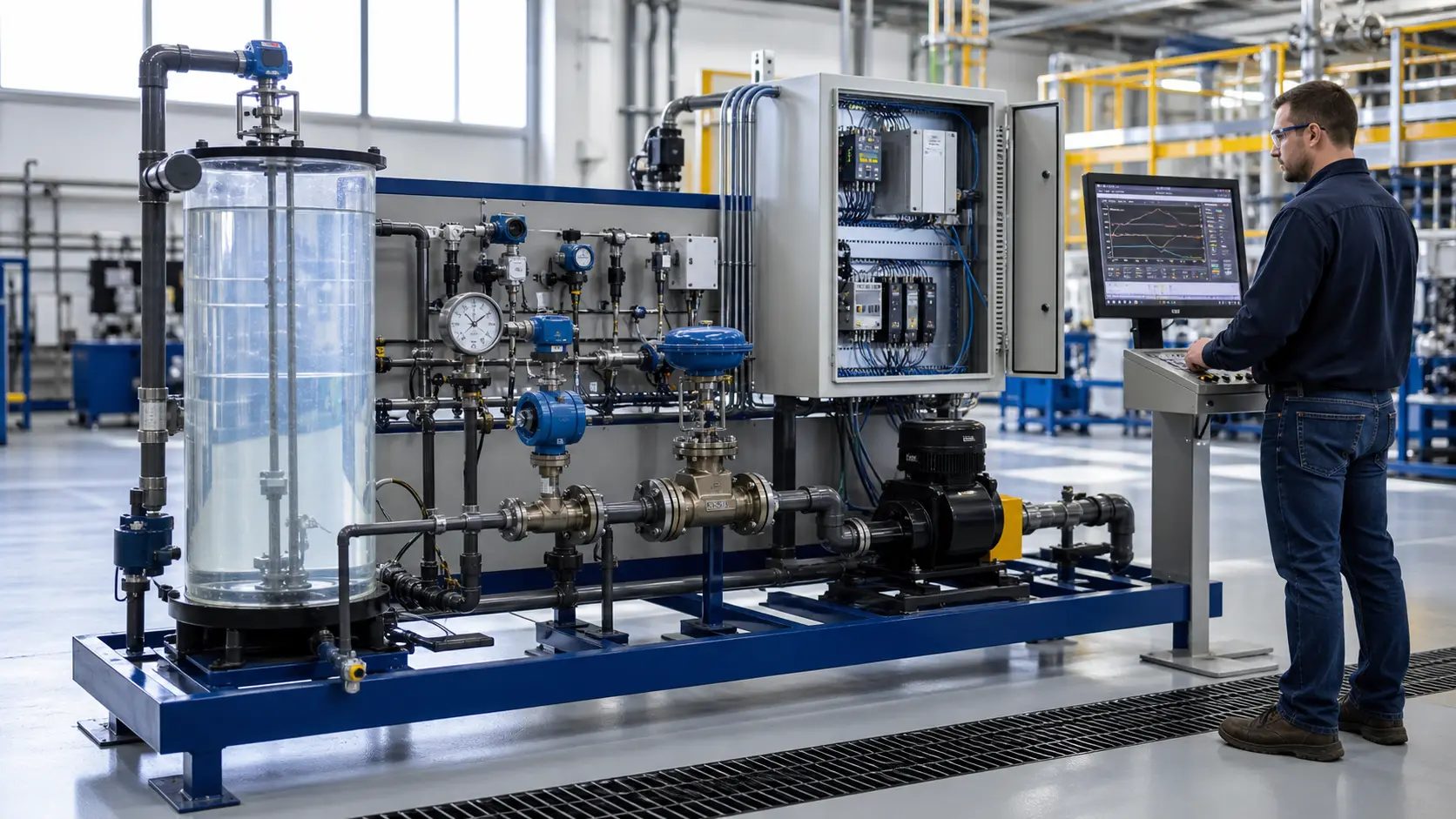
PLC programming interviews vary widely — from a quick "tell me about a project" conversation to a 90-minute technical screen with live coding. But most interviewers draw from the same pool of fundamentals.
The 25 questions below cover scan behavior, ladder logic, timers, counters, PID, safety, troubleshooting, and industrial communications. Treat each answer as a framework, not a script: state the principle, explain how you would verify it on the target controller, and connect it to a machine example you can defend.
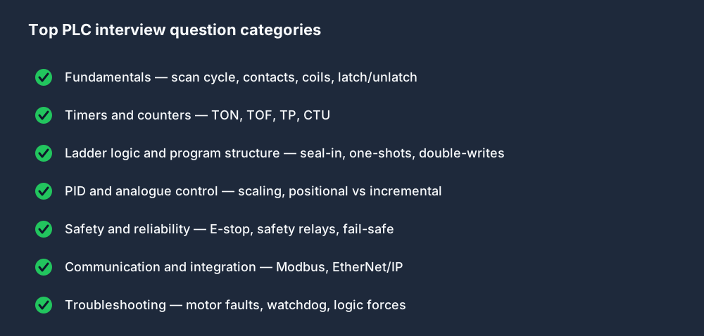
Almost every PLC interview draws from the same handful of topic areas. Knowing where the questions come from helps you target your prep.
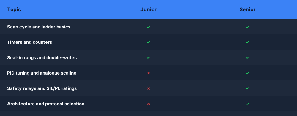
How deep an interviewer goes usually tracks the seniority of the role.
What PLC interviewers are actually testing
A strong answer proves three things: you understand the controller model, you can connect code to field equipment, and you know when a safety or vendor-specific detail must be verified rather than guessed. Junior PLC technician interviews emphasize I/O, contacts, coils, timers, and a methodical fault trace. Controls engineer and PLC programmer interviews go deeper into architecture, state, networking, change control, and commissioning risk. Siemens and Allen-Bradley interviews add platform terminology, but the underlying control reasoning remains transferable.
Fundamentals
1. What is a PLC and what problem does it solve?
A PLC (Programmable Logic Controller) is a ruggedised industrial computer that replaces relay panels and hardwired logic with a programmable control program. It solves the problem of maintaining and modifying complex sequencing and interlock logic: instead of rewiring a relay cabinet every time the process changes, you update software. PLCs also provide deterministic execution timing, industrial environmental ratings, and integration with SCADA and HMI systems.
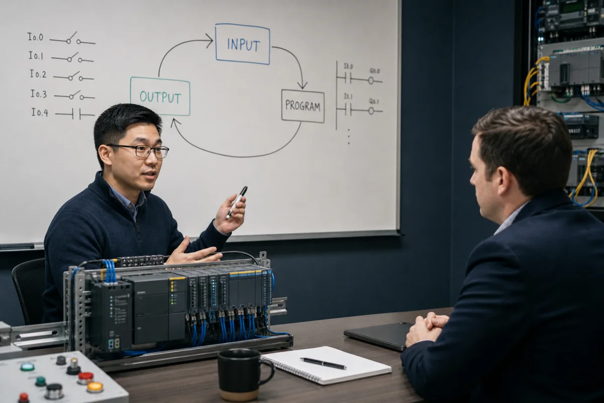
2. Describe the PLC scan cycle.
The scan cycle has three main phases:
- Input scan — all input states are read into the Process Image Input Table.
- Program execution — the CPU evaluates each rung/instruction top to bottom, writing results to the Process Image Output Table.
- Output scan — the output image table is written to the physical output terminals.
A fourth phase, often described as housekeeping, handles controller services such as communications and diagnostics. The exact order, task model, process-image behavior, and scan time depend on the controller family and configuration, so a senior answer names the target platform before assuming a timing value.
See also: The PLC Scan Cycle Explained
3. What is a normally-open vs a normally-closed contact?
A ladder instruction examines a Boolean value; it is not the same thing as the physical contact on the device. In Allen-Bradley terminology, XIC passes rung continuity when the referenced bit is 1 and XIO passes when the bit is 0. IEC editors commonly draw normally-open and normally-closed contact symbols with the same Boolean behavior.
A physical stop device is often wired so the healthy circuit is energized and a press or broken wire removes the signal, but the ladder instruction you use depends on how the input tag represents that field state. For a safety function, do not infer adequacy from one PLC contact symbol: the risk assessment, device architecture, diagnostics, safety controller or relay, output devices, and validation determine the design.
4. What is a coil in ladder logic?
A coil is the output element on the right side of a rung. When the rung conditions are true, the coil bit is set to 1. When the rung is false, the coil is set to 0. Special coil types include latch (set), unlatch (reset), and one-shot (pulse for one scan only).
5. Explain the difference between OTL/OTU (latch/unlatch) and a standard coil.
A standard output coil (OTE in AB, ( ) in IEC) reflects the current rung state every scan — if the rung is false, the bit is 0. An OTL (latch) coil sets the bit and it stays set when that rung goes false until an OTU (unlatch) instruction clears it. Whether a value survives a power cycle, download, prescan, or controller mode change is platform- and configuration-specific. Use explicit initialization and safe-start logic rather than assuming retentive behavior.
Timers and Counters
6. What is a TON timer and how does it work?
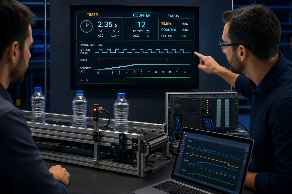
TON (Timer On-Delay) starts timing when its enable input goes TRUE. After the preset time (PT) elapses, the done output (Q) goes TRUE. If the enable drops before PT, the timer resets. Key parameters: IN (enable), PT (preset), Q (done), ET (elapsed time).
Use it when something must happen after a delay — e.g., a motor run-time confirmation alarm after 5 seconds of no feedback.
7. What is a TOF timer? When would you use it over TON?
TOF (Timer Off-Delay) — the output Q is TRUE when the enable is TRUE. When the enable drops to FALSE, the timer starts, and Q stays TRUE for the preset duration before dropping. Use it for post-run actions: a motor cooling fan that stays on for 30 seconds after the motor stops.
8. What is a TP timer?
TP (Timer Pulse) generates a fixed-width pulse on Q for exactly PT time after a rising edge on the enable input, regardless of how long the input stays active. Use it to generate a consistent timed output from an uncontrolled input.
9. What does the CTU counter do?
CTU (Count Up) increments its accumulated value CV by 1 on each rising edge of the count input CU. When CV >= PV (preset value), the output Q goes TRUE. A reset input R clears CV to 0. Use it to count parts, cycles, or events.
10. How do you reset a timer that has timed out?
For TON: remove the enable input (set it to FALSE for at least one scan). The timer resets immediately when the enable drops. For CTU: apply a TRUE to the reset input R. On AB platforms, the reset instruction (RES) is applied to the timer or counter tag.
Ladder Logic and Program Structure
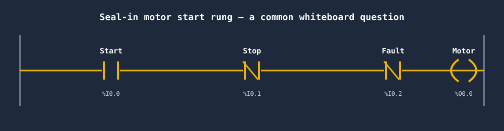
11. What is a seal-in rung? Draw one in pseudocode.
A seal-in rung keeps an output latched after a momentary start signal is released:
|--[Start]--+--[/Stop]--[/Fault]--( Motor )--|
            |
            +--[Motor]--+
Once Motor energises, its own NO contact in the parallel branch maintains the rung even when Start opens. Stop or Fault breaks all paths and de-energises the motor.
More detail: Seal-In Rungs in Ladder Logic: The Complete Guide
12. What is the difference between a contact and a coil?
A contact is an input condition — it reads a bit and determines whether logic flows. A coil is an output action — it writes a bit. In a sentence: contacts on the left side of a rung determine whether the coil on the right side is energised.
13. What happens if two rungs write to the same output bit?
In a conventional cyclic task with ordinary writes, the later executed write is the value left for the output update. But task priority, immediate I/O instructions, asynchronous modules, aliases, and vendor execution rules can change what “last” means. Duplicate writes are therefore difficult to reason about. Consolidate ownership of a commanded output and verify execution order on the target platform.
14. What is a one-shot instruction (OSR / R_TRIG)?
A one-shot rising-edge instruction outputs TRUE for exactly one scan when its input transitions from FALSE to TRUE. It is used to trigger an action that must happen only once per button press, rather than every scan the button is held. IEC equivalent: R_TRIG function block. AB: ONS or OSR instruction.
PID and Analog Control
15. What is a PID controller in a PLC context?
A PID (Proportional-Integral-Derivative) controller is a closed-loop control algorithm that drives a process variable (temperature, pressure, level, flow) toward a setpoint by computing an output (heater power, valve position) based on:
- P (Proportional): output proportional to current error.
- I (Integral): output proportional to accumulated error over time (removes steady-state offset).
- D (Derivative): output proportional to rate of error change (dampens overshoot).
See PID Control for PLCs: Practical Tuning Guide
16. What is the difference between a velocity (incremental) PID and a positional PID?
A positional PID computes an absolute controller output. An incremental (velocity) PID computes the change to apply each sample. Neither form is inherently safe: bumpless transfer, initialization, output tracking, limits, anti-windup, controller mode changes, and the actuator fail position determine transition behavior. A good answer asks how the vendor block handles those conditions.
17. What does analog scaling mean?
A physical 4–20 mA signal representing 0–100°C is converted by the input module into a raw or already-engineered value. The raw endpoints vary by module and configuration, so read the channel documentation first. The general equation is EU = (Raw - RawLow) / (RawHigh - RawLow) × (EUHigh - EULow) + EULow, with separate handling for underrange, overrange, bad quality, and a broken loop.
Safety and Reliability
18. What is the difference between fail-safe and fail-secure?
- Fail-safe — on fault, the system moves to a state that is safest for people and equipment. For most machines, that means de-energising outputs (stopping motion, closing valves).
- Fail-secure — on fault, the system maintains physical security (a door stays locked). This may mean the output stays energised on fault.
The appropriate behavior depends on the hazard. A lift motor is fail-safe (stops on fault). An electronic lock on a pharmaceutical isolator may be fail-secure.
19. Why is a standard PLC input not enough for an E-stop?
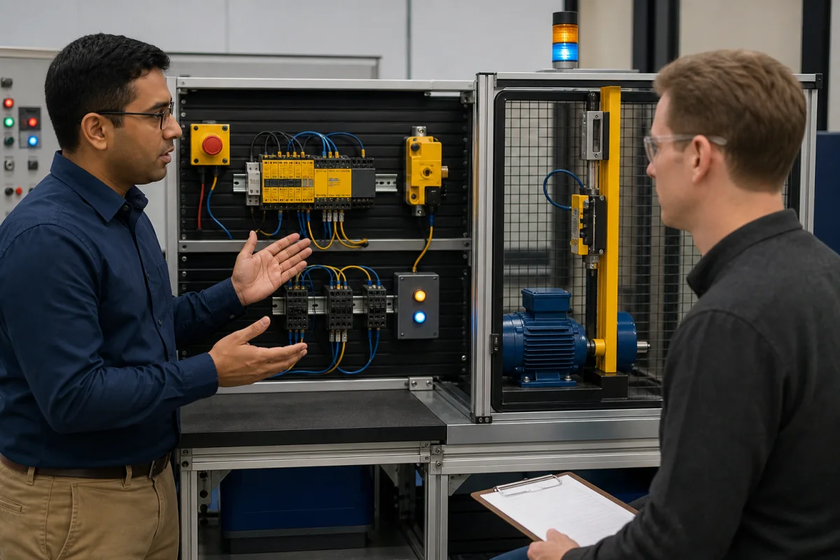
A standard PLC input and ordinary program do not provide the diagnostic coverage, fault tolerance, verification, or validated performance required of a machine safety function. Depending on the risk assessment, the E-stop function may use a safety relay or a safety-rated PLC with dual-channel inputs, safety logic, monitored outputs, and contactor feedback. The ordinary control PLC may receive a status signal for diagnostics, but it must not be mistaken for the complete safety function.
20. What is a safety relay and how does it differ from a standard relay?
A safety relay is designed for safety functions and typically provides monitored dual-channel inputs, fault detection, controlled reset behavior, and safety outputs suitable for an assessed architecture. A standard control relay does not provide the same documented safety characteristics. The relay alone does not make a circuit safe: device selection, wiring, output contactors, feedback, calculated performance level or SIL, and validation all matter.
Communication and Integration
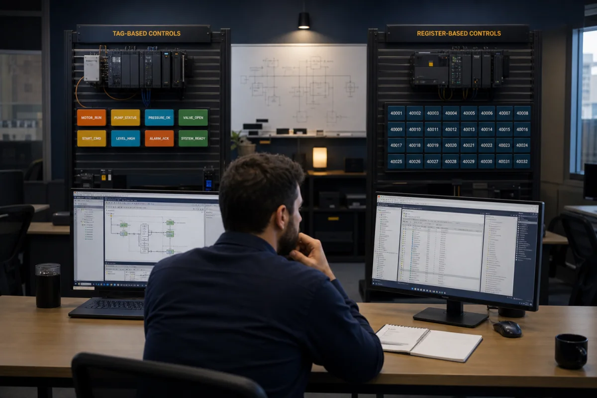
21. What is Modbus and how is it used with PLCs?
Modbus is a serial communication protocol published in 1979 and still widely used. Modbus RTU runs over RS-485 or RS-232. Modbus TCP runs over Ethernet. A PLC acts as a Modbus master (client) to read registers from slave (server) devices — VFDs, sensors, meters, remote I/O. Registers: coils (bits, writable), discrete inputs (bits, read-only), holding registers (16-bit words, writable), input registers (16-bit words, read-only).
22. What is EtherNet/IP and how does it differ from standard TCP/IP?
EtherNet/IP (Ethernet Industrial Protocol) runs over standard TCP/IP and UDP/IP infrastructure but adds the CIP (Common Industrial Protocol) application layer. It supports implicit (cyclic I/O data, UDP) and explicit (message-based, TCP) connections. Allen-Bradley uses EtherNet/IP natively. It differs from standard TCP/IP in that it defines industrial device profiles, real-time I/O exchange semantics, and a device identity model — Ethernet is just the physical/transport layer.
Troubleshooting
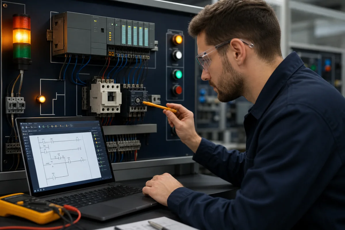
23. A motor is not starting. Walk through your troubleshooting process.
- Make the diagnostic state safe — establish who controls the machine, identify hazardous energy, and use the site procedure and lockout/tagout when the work requires exposure or servicing.
- Confirm the symptom and command path — what mode is selected, what command is expected, and what feedback should return?
- Trace from the commanded output backward — program command, interlocks and permissives, input image, module status, and field device state.
- If the command is present but the motor is stopped — with the approved safe test procedure, inspect output/module diagnostics, control power, overload state, contactor command and feedback, drive faults, and the power circuit.
- Verify the repair — remove temporary test conditions, clear authorized forces, restore guards, test normal stop and fault behavior, and document the cause.
24. What does the watchdog timer do?
A watchdog detects when a task or scan exceeds an allowed execution time and faults or invokes the controller-specific response. What happens next depends on the controller, task, fault handler, module connection behavior, and output configuration; do not promise that every physical output automatically reaches a process-safe state. Safety functions need their own assessed architecture.
25. What is a logic force and why is it dangerous?
A force overrides or substitutes a value in a platform-specific part of the controller/I/O path. It can be useful during controlled commissioning and diagnostics, but it is dangerous because:
- Force indicators can be missed outside the engineering tool or by another shift, so the machine state may no longer match what a technician expects from field signals.
- Forgetting to remove a force can mask a real hardware fault.
- Forcing safety inputs can defeat safety interlocks.
Never use a force as a substitute for energy isolation or safety validation. Follow the site authorization and energy-control procedure, record the exact force, maintain control of the test, remove it deliberately, and verify the controller and machine state before return to service.
Practice Before Your Interview
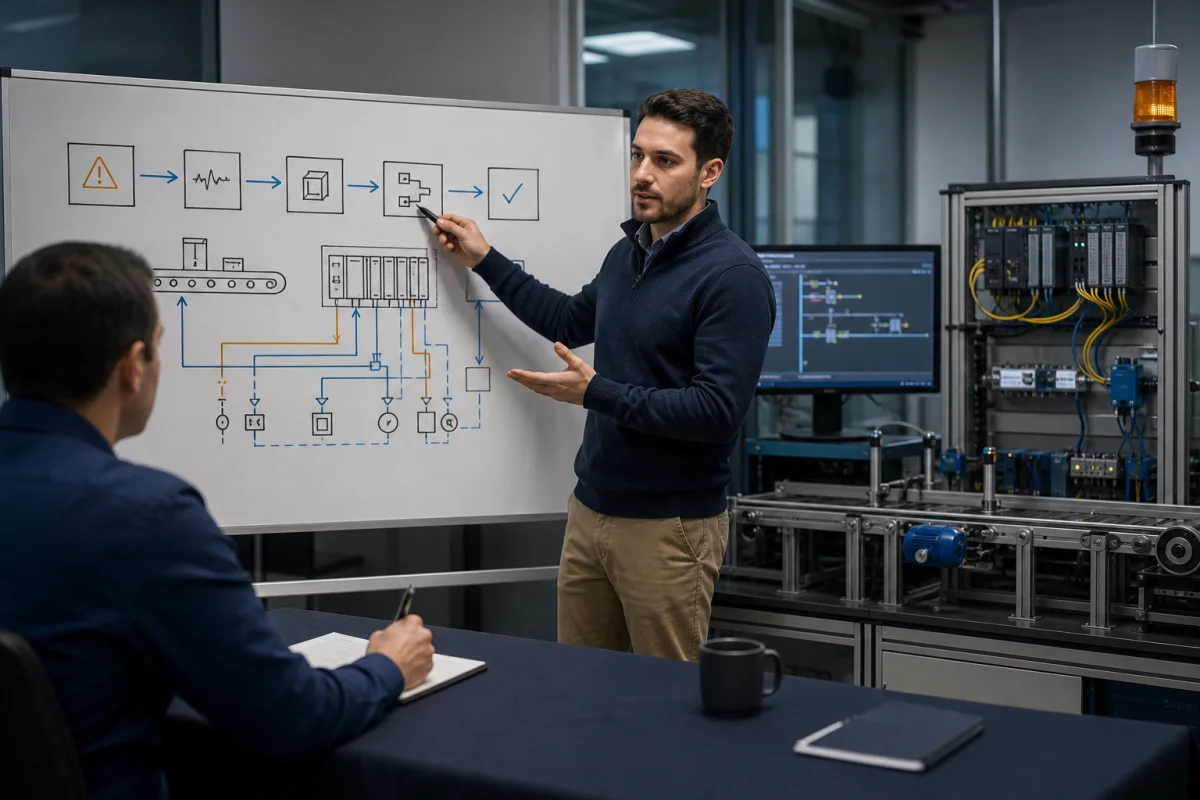
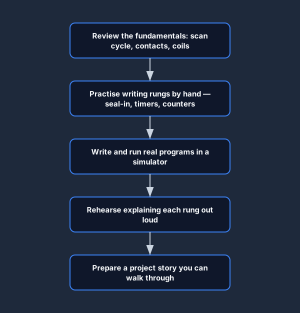
The best preparation for a PLC interview is writing real programs and being able to explain what each rung does and why. Use this preparation flow to build up from the fundamentals to a project story you can walk through on the day.
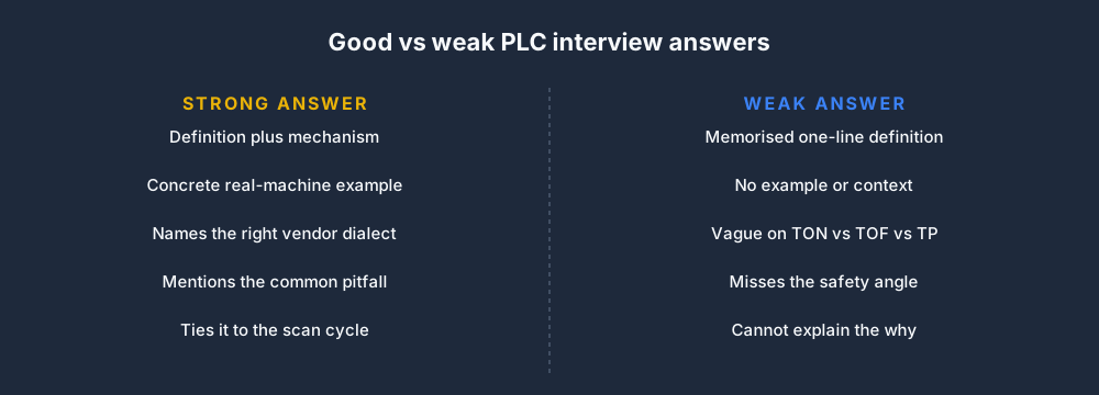
When you do answer a question, structure it so you show depth, not just a memorized definition.

The difference between a strong answer and a weak one is usually context — an example, a dialect, and a pitfall.
Work through the interview prep tracks in the PLC Simulator's interview prep section — they combine technical questions, live coding exercises, and timed practice. They are independent practice tools, not replicas of any employer's interview.
For more on career paths, read How to Become a PLC Programmer: A Self-Teaching Roadmap.
Frequently asked questions
What questions are asked in a PLC interview?
Expect questions about the scan cycle, digital I/O, contacts and coils, timers and counters, motor starters, interlocks, troubleshooting, safety boundaries, and one project you can explain. Controls engineer roles add architecture, networking, analog control, change management, and commissioning judgment.
How should a beginner prepare for a PLC interview?
Learn the scan and I/O model, build a motor start/stop rung, practice a timer and counter, then rehearse one structured fault trace. Say what you would verify on the actual controller instead of bluffing a vendor-specific detail.
Are Siemens and Allen-Bradley PLC interview questions different?
The control principles overlap, but terminology, addressing, project structure, task execution, diagnostics, and instruction behavior differ. Prepare the platform used by the employer and translate each vendor term back to the underlying control concept.
Do PLC interviews include a practical test?
Some do. A practical exercise may ask you to read a rung, build a seal-in circuit, diagnose a missing permissive, explain I/O, or talk through a commissioning fault. Confirm the employer's format when the recruiter can share it.
Can an online PLC simulator replace hardware interview preparation?
No. A simulator is useful for repeated logic, sequencing and diagnosis practice. Hardware work adds electrical safety, measurements, wiring, network setup, drive configuration, commissioning and the physical consequences of a control decision.
Primary references
- Rockwell Automation: Studio 5000 bit instructions
- Siemens: S7-1200 system manual and PLC concepts
- Rockwell Automation: machine safety technical documentation
- OSHA: control of hazardous energy (lockout/tagout)
Practice the first PLC program without an account. No install or credit card. Build a contact-and-coil rung, run it, operate the input, and explain the output state.