Motion and state
Its rotary state can be driven from a PLC output so speed and direction remain visible during a scan.
sensors · rotary model
A PLC rotary encoder converts shaft rotation into electrical pulses. An incremental quadrature encoder provides channels A and B ninety electrical degrees apart, letting a high-speed counter determine direction as well as movement. The program turns accumulated counts into position, speed or travelled distance using pulses per revolution, mechanical ratio and a defined reference point.
Create a free account to run this scenario, or try a PLC lab now — no signup.
Explore Rotary encoder in 3D
Load the interactive model when you are ready to rotate, inspect and operate it. Deferring WebGL keeps the reference page fast.
Its rotary state can be driven from a PLC output so speed and direction remain visible during a scan.
Commission it by proving active feedback before accepting enable.
Inject stuck-on, stuck-off, misaligned states and require the PLC sequence to detect, stop and recover deliberately.
PLC integration guide
Encoder pulses can change faster than the normal PLC scan can sample. Wire the channels to inputs and instructions specifically rated for the required frequency, then configure the counter mode for A/B quadrature and the desired multiplication. A normal contact instruction may miss edges even though it appears to work at hand-turned speed. Shielding, grounding and differential signalling matter as cable length and electrical noise increase.
Document the encoder resolution, whether the counter uses one, two or four edges per cycle, gearbox ratio, wheel circumference and sign convention. Position is accumulated counts divided by counts per engineering unit. Speed is count change over a stable sample interval. Avoid burying these constants across rungs; keep them together and expose raw count, scaled value and status for diagnosis.
An incremental encoder does not inherently know absolute position after power loss. Use a home sensor, index pulse or retained position strategy that matches the machine. Handle counter rollover and reverse motion mathematically. When motion is commanded, compare the expected count change with a timeout or following-error band so a broken coupling, damaged cable or stalled shaft becomes a meaningful fault.
The reference above focuses on PLC integration. The interactive school lesson shows the device, signal or mechanism before you write the control sequence.
Open the quadrature encoder signal labSignal map
PLC output Enable; PLC input Active feedback
| Signal | PLC direction | Type / range |
|---|---|---|
| Enable enable | output | bool |
| Active feedback active | input | bool |
Field checklist
Fault finding
| Symptom | Check |
|---|---|
| Count direction is reversed | Swap A and B only if permitted by the wiring design, or change the configured direction convention consistently. |
| Counts are missed at speed | Check input frequency rating, filter time, high-speed-counter configuration, cable shielding and signal level. |
| Position is correct near zero but drifts with travel | Verify pulses per revolution, edge multiplier, gearing, circumference and mechanical slip. |
Fault and recovery exercise
Inject stuck-on, stuck-off, misaligned states and require the PLC sequence to detect, stop and recover deliberately.
The model teaches PLC sequence behaviour and diagnosis. Confirm ratings, wiring, guarding, process calculations and commissioning limits against the real manufacturer documentation and site design.
Plain-English answers
Their phase relationship reveals direction. The sequence of A and B edges changes when the shaft reverses.
Pulses per revolution describes the base signal cycles. A quadrature counter may count multiple edges per cycle, so configured counts per revolution can be higher than the stated PPR.
The encoder provides relative movement. Absolute machine position normally requires homing, an index strategy, retained state with validation, or an absolute encoder.
Free first success
Open a related browser scenario, run the PLC logic and see the component state respond. Start without installing software or entering a card.
Keep building
sensors
Its visible state changes with simulated I/O, making status and diagnosis readable in the scene.
sensors
Its visible state changes with simulated I/O, making status and diagnosis readable in the scene.
sensors
Its visible state changes with simulated I/O, making status and diagnosis readable in the scene.
Technical reference and worked-example guide
Direct answer
The reader can define pulses per revolution, electrical interface and expected channel sequence, then distinguish motion, wiring, count and scaling faults.
Written for automation learners and technicians connecting incremental encoder channels, direction, count, speed and reference behavior to PLC inputs.
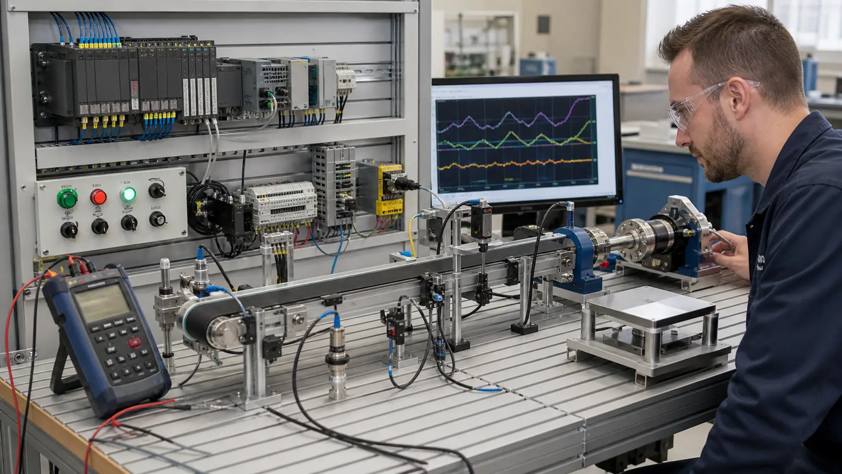
Motion range, shaft speed, pulses per revolution, A/B/Z channels, electrical output, supply, input frequency, shielding, count mode, units and reference policy.
Shaft motion through encoder channels, cable and input circuit to edge count, direction, scaled position or speed and independent physical check.
Known clockwise and counter-clockwise turns with repeatable counts, direction and scaled engineering result.
Maximum frequency, slow edge, reversed channels, lost pulse, noise, index crossing, count rollover, restart and mechanical slip.
A mechanical, supply, signal-level, channel-order, input-filter, count, scaling, reference or feedback mismatch.
The selected encoder and high-speed input verified across the real speed range and installed wiring.
Match the encoder supply and output type to a compatible input, route A/B and optional index channels correctly, then configure counting and scaling within documented frequency limits.
Quadrature A and B channels are phase shifted; their edge order indicates direction when wiring and count mode are configured consistently.