← Back to all lessons
Fault 14
Pro

Fault 14 — Reversed Thermocouple Polarity

What you'll learn

**Reported symptom:** The indicated temperature falls when the process heats up and rises as it cools.

Lab time: ~10 minutes.

Lesson briefing

Reversed Thermocouple Polarity

Reported symptom: The indicated temperature falls when the process heats up and rises as it cools.

The circuit was commissioned from a known-good drawing. Treat every terminal as suspect, but test from source to load instead of guessing. Use voltage mode on an energised control circuit and continuity only after the simulated circuit is isolated.

Your task

Verify sensor polarity at the input card against the thermocouple type and extension-wire markings.

Choose the fault category only when the measurements support it.

Hints

Hint 1

Do not rely on generic red/black conventions; thermocouple colours vary by standard and type.

Hint 2

Sign up to unlock the full hint sequence.

Hint 3

Sign up to unlock the full hint sequence.

This lesson uses 7 placed components on the lab canvas. Components are vendor-neutral (no proprietary trademarks); the wiring rules apply to any equivalent industrial part.

Sign up to preview

Create a free account to preview this Pro lab; upgrade to open the interactive circuit.

Sign up to preview →
You might also like

Competency and practice field guide

Reversed thermocouple fault lesson: practice plan

Direct answer

The learner can preserve the symptom, compare process and tag direction, isolate polarity at a safe boundary and prove repair with more than one known condition.

Written for instrumentation and maintenance learners diagnosing a temperature that moves in the wrong direction or reads implausibly after installation or maintenance.

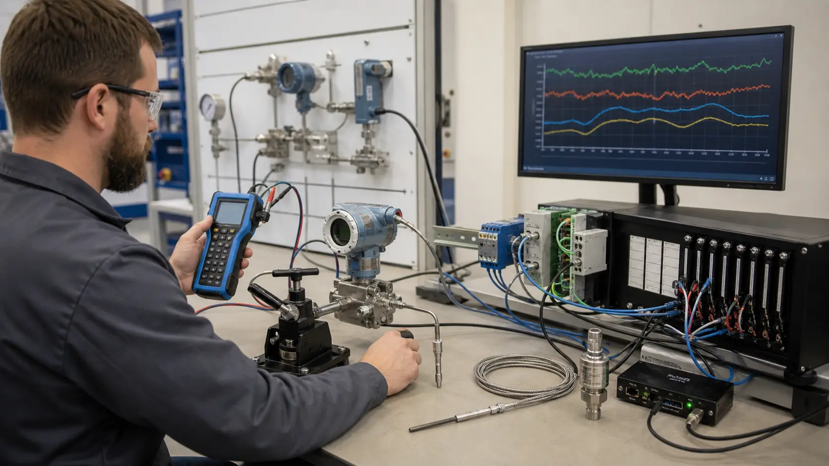
an instrumentation diagnostics bench connecting pressure, temperature and smart transmitters to isolated analog channels and time-aligned trend evidence while studying reversed thermocouple diagnosis and corrective proof
System map / 02

NODE 01observable

Scope

Actual process direction, sensor type, conductor polarity and color convention, extension cable, junction locations, input type, cold-junction compensation, trend history and safe isolation.

NODE 02observable

Signal path

Temperature change through hot-junction voltage, conductor path, module terminals, conversion, compensation, engineering tag and independent temperature reference.

NODE 03observable

Baseline practice

A controlled temperature increase produces a repeatable increase in the displayed value across two or more known points.

NODE 04observable

Edge cases

Ambient crossover, small gradients, mixed conductor types, loose terminal, wrong module type, compensation error, open circuit and stale value.

NODE 05observable

Fault practice

A process-reference, sensor, polarity, conductor, junction, terminal, module, compensation, scaling or display mismatch.

NODE 06observable

Transfer to the job

The corrected polarity inspected and verified under approved procedure with reference evidence and affected alarms and control functions retested.

Answer surface / 07

What happens when a thermocouple is wired backwards?

Its thermoelectric contribution has the wrong polarity, so the indicated temperature commonly moves in the wrong direction relative to the measurement junction.

How do you confirm reversed thermocouple polarity?

Compare the configured type and terminal markings, trace conductor materials, then apply a safe known temperature change and verify direction at multiple points.