What you'll learn
Connect a low-level thermocouple signal directly to a temperature input card with correct polarity and a single-point shield. Thermocouple extension wire must match the sensor type all the way to the cold-junction compensation terminals.
Lab time: ~15 minutes.
Lesson briefing
Thermocouple Input and Shielding
Connect a low-level thermocouple signal directly to a temperature input card with correct polarity and a single-point shield. Thermocouple extension wire must match the sensor type all the way to the cold-junction compensation terminals.
The device in the real world
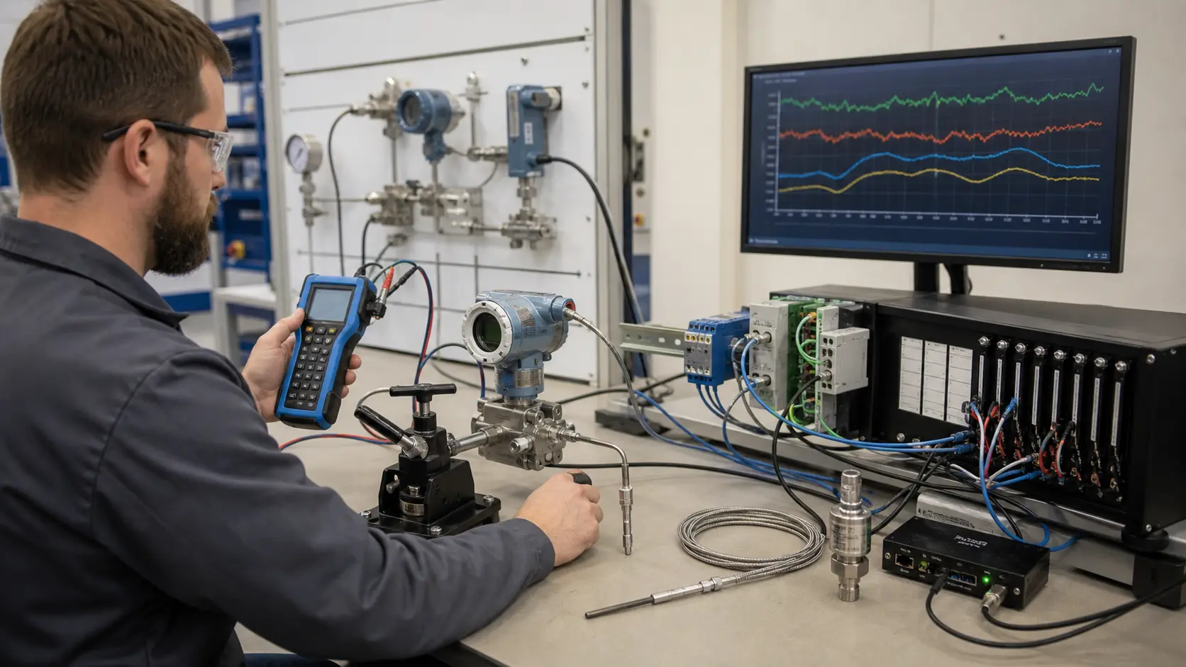
Thermocouples sit in kilns, ovens, extruders and furnaces where RTDs cannot survive. Two dissimilar metals joined at the hot end produce a few millivolts that rise with temperature. The input card measures that tiny voltage and adds its own cold-junction reading to work out the temperature, so the connection between probe and card must be made with the matching extension wire, not ordinary copper.
Why it is wired this way
A thermocouple generates millivolts; reversing its polarity makes temperature trend in the wrong direction. Ordinary copper splices introduce extra junctions and temperature-dependent error.
Worked example
A type K thermocouple in an oven produces about 4.1 mV at 100 degrees C and about 8.1 mV at 200 degrees C, measured against a 0 degree C reference junction. Those are millivolts, so a mistake of a few millivolts moves the reading by many degrees. If the + and - leads are swapped, heating the oven makes the displayed value fall, which is a typical symptom reported on site. Wire the lab by landing the sensor plus on TC+ and the minus on TC-, then bonding the shield at the card end only so that the screen drains noise without becoming part of the signal.
Common mistakes
- Assuming red is always positive. Colour codes differ between national standards and thermocouple types, so use the markings for your type.
- Joining the extension cable with ordinary copper terminals, which adds extra junctions.
- Earthing the shield at both ends.
- Running the thermocouple pair alongside a drive output cable.
What you can now do
You can connect a thermocouple with correct polarity and shield, and explain why wire type matters all the way to the card.
Commissioning standard
Warm the probe slightly by hand and check that the displayed temperature rises, then confirm the shield has continuity to earth at one end only.
Hints
Power the card from the 24 V bus before commissioning the channel.
Sign up to unlock the full hint sequence.
Sign up to unlock the full hint sequence.
This lesson uses 7 placed components on the lab canvas. Components are vendor-neutral (no proprietary trademarks); the wiring rules apply to any equivalent industrial part.
Sign up to preview
Create a free account to preview this Pro lab; upgrade to open the interactive circuit.
Sign up to preview →