Drive and prove
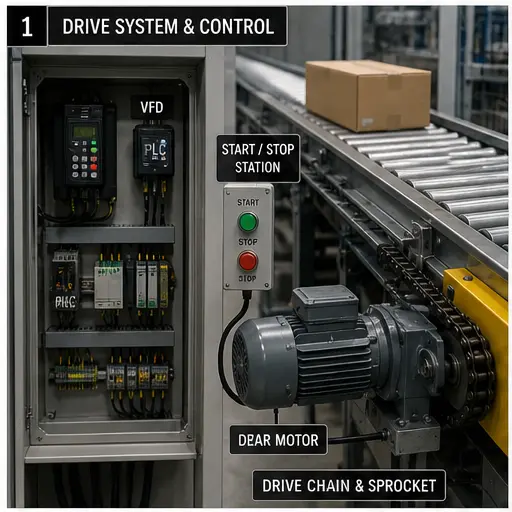
Issue a run demand only after permissives; compare commanded speed with running and encoder feedback.
PLC conveyor system
A complete conveyor programme coordinates drives, sensors, product memory, routing, accumulation, protection and recovery. Build each layer, then prove it on a running 3D line.
Conveyor control in context
A complete conveyor program owns motion, detection, tracking, routing, accumulation, fault evidence and restart behavior. These views define the practical boundaries the runnable scenarios teach.
Control architecture
Issue a run demand only after permissives; compare commanded speed with running and encoder feedback.
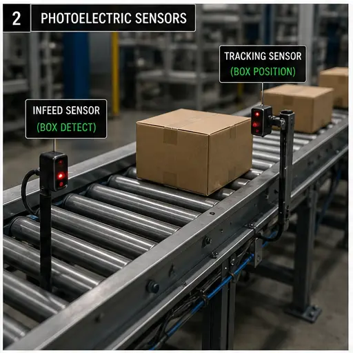
Debounce sensors, capture arrival edges and preserve product identity between physical detection points.
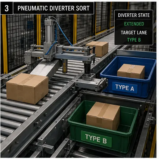
Coordinate stops, pushers, turntables and diverters without colliding loads or losing the tracked destination.
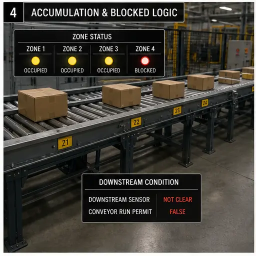
Detect jams, failed feedback and blocked discharge; stop in a defined order and require deliberate reset.
Runnable curriculum
Track products between detection and diversion with counters and timing.
Open scenarioSee motion, sensor state and diversion on the same editable factory floor.
Open scenarioCommand, scale and prove belt speed from analog and discrete signals.
Open scenarioKeep discharge moving long enough to clear the last product safely.
Open scenarioSequence downstream-first and protect a bulk-material line from blockage.
Open scenarioRestore the drive only after the unsafe demand and original cause are gone.
Open scenarioOpen each object to inspect its motion, typed PLC points, failure modes and scenarios before composing the line.
Training models teach sequence, state and fault reasoning. Real conveyor design still requires load, motor, braking, guarding, stop-category, safety distance and manufacturer calculations.
Conveyor controls field guide
Direct answer
A PLC conveyor system coordinates energy, motor or drive control, product detection, zone occupancy, tracking, routing, jams, downstream availability and controlled restart. Reliable logic separates the command to move from feedback that products and equipment actually moved.
This guide is written for pLC learners and controls technicians designing or diagnosing material-handling sequences. The intended result is specific: the learner can map a conveyor into zones, track product identity, arbitrate transfers, detect missing transitions and recover from jams without losing state or creating automatic hazardous motion.
System map / 02
Treat these as connected checkpoints. Each checkpoint has an expected state, an observable state and a boundary to the next part of the system. That structure prevents a software indication from being mistaken for physical proof.
Separate run and speed request from drive ready, running, current, speed and fault feedback.
Each zone needs occupied, available, blocked, transferring and fault meaning rather than one ambiguous photoeye bit.
Identity advances only on proven transitions and must handle gaps, accumulation, reject and restart.
A diverter command depends on classification, product position, actuator readiness and destination availability.
Use an expected transition and a time or motion boundary, not simply a sensor that remains on.
Reconcile product positions and downstream capacity before restoring automatic flow.
Procedure / 03
Run the steps in order the first time. Later, the same structure becomes a diagnostic loop: define the expected condition, observe the boundary, interpret the difference and choose one proving action.
Identify infeed, zones, transfers, drives, sensors, actuators and destinations.
Evidence: A material-flow diagram names every boundary.
Avoid: Writing code from the I/O list alone.
Specify empty, occupied, requesting, transferring, blocked and fault conditions.
Evidence: Each zone has one coherent owner.
Avoid: Using scattered latches without a model.
Test ready, run, speed, stop and fault behavior.
Evidence: Command and feedback are distinct.
Avoid: Assuming output equals motion.
Advance identity on a verified sensor sequence.
Evidence: No duplicate or lost item occurs.
Avoid: Incrementing on a held level.
Block downstream and fill zones deliberately.
Evidence: Transfers stop without collisions.
Avoid: Testing only free-flow production.
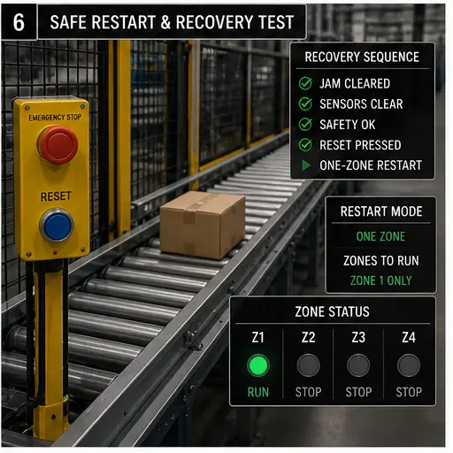
Remove cause, inspect positions, reset and restart one transfer at a time.
Evidence: State and physical products agree.
Avoid: Clearing every bit blindly.
Diagnostic matrix / 04
The table is a reasoning aid, not a parts-replacement chart. Preserve the initial symptom, inspect the named boundary and use the interpretation to choose the next controlled test. Site safety procedures and equipment manuals remain authoritative.
| Observed symptom | Inspect | Interpretation | Next proving action |
|---|---|---|---|
| Motor command on, belt stopped | Drive ready/run, frequency, current, coupling and load | The failure is beyond PLC command. | Trace drive and mechanics. |
| Photoeye stays blocked | Product presence, alignment, contamination, wiring and input | A real product and a failed sensor can look identical to logic. | Use independent observation. |
| Count is wrong | Edge logic, sensor spacing, bounce and product recirculation | The event definition is unstable. | Capture transitions. |
| Diverter sends wrong item | Tracking index, classification timing, position and actuator feedback | Identity and physical product lost synchronization. | Replay one item slowly. |
| Zones collide | Downstream-available contract and transfer ownership | Two zones may command the same space. | Centralize arbitration. |
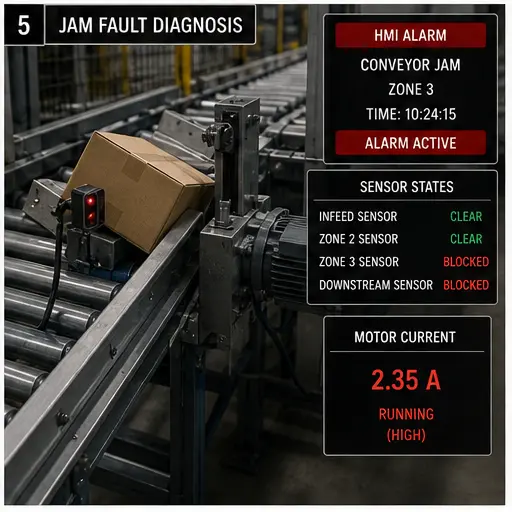
| Jam returns after reset | Root cause, retained product state and timeout trigger | Reset removed indication but not cause. | Prove motion before clearing. |
Product evidence / 05
The platform includes conveyor scenarios with motors, VFD references, sensors, counters, diverters, product physics, jams and behavioral grading.
The browser model does not select guards, safety functions, drives, motors, braking, protection or mechanical design for a real conveyor. Those require qualified engineering and equipment validation.
Field notes / 06
Conveyor controls become difficult when product identity and physical location are treated as an afterthought. Define exactly when a product enters the model, which sensor transition transfers ownership, how empty gaps are represented and what happens when a product is removed manually. A sequence that works in uninterrupted flow can fail immediately after a jam because retained counters, queue positions and real cartons no longer agree.
Use commissioning cases that deliberately create the states production dislikes: downstream unavailable, photoeye blocked, drive fault during transfer, diverter late, encoder stopped and power restored with occupied zones. The expected result is not always continued production. A good program stops the affected motion, preserves useful state, tells the operator which boundary failed and provides a controlled route back to a coherent material-flow model.
Commissioning notebook / 06
Use these as written briefs rather than click-through instructions. For every case, state the expected condition before acting, retain the first useful observation and explain why the final result proves the requirement. A different program or component choice can still be correct when it produces the same bounded behavior and evidence.
Case 01
predict → observe → prove
Engineering context. Separate run and speed request from drive ready, running, current, speed and fault feedback. Begin with a written normal condition and identify which request, state, physical result or communication value will provide independent confirmation. Do not begin by changing the configuration; the initial state is part of the evidence and should remain reproducible.
Controlled setup. Use the “Map mechanics” stage of the workflow: identify infeed, zones, transfers, drives, sensors, actuators and destinations. The acceptance record should show this result: a material-flow diagram names every boundary. Record initial conditions, the exact stimulus and the observation point so another learner can repeat the case without relying on your memory.
Fault challenge. Introduce or analyse “Motor command on, belt stopped” as one bounded deviation. Inspect drive ready/run, frequency, current, coupling and load The working interpretation is that the failure is beyond PLC command. The next proving action is to trace drive and mechanics. Change only one condition before observing the result, and preserve timestamps or measurements where timing matters.
Review and recovery. The most common trap here is writing code from the I/O list alone. After restoring the cause, repeat the normal case and at least one stop, timeout, disconnect or restart boundary relevant to this topic. Remove temporary forces and bypasses, return the model to a known state and retain the evidence that both operation and recovery are deliberate.
Explain it aloud: How does a PLC control a conveyor? A defensible short answer is: It evaluates commands, permissives, sensors and state, then controls starters or drives and monitors feedback.
Case 02
predict → observe → prove
Engineering context. Each zone needs occupied, available, blocked, transferring and fault meaning rather than one ambiguous photoeye bit. Begin with a written normal condition and identify which request, state, physical result or communication value will provide independent confirmation. Do not begin by changing the configuration; the initial state is part of the evidence and should remain reproducible.
Controlled setup. Use the “Define states” stage of the workflow: specify empty, occupied, requesting, transferring, blocked and fault conditions. The acceptance record should show this result: each zone has one coherent owner. Record initial conditions, the exact stimulus and the observation point so another learner can repeat the case without relying on your memory.
Fault challenge. Introduce or analyse “Photoeye stays blocked” as one bounded deviation. Inspect product presence, alignment, contamination, wiring and input The working interpretation is that a real product and a failed sensor can look identical to logic. The next proving action is to use independent observation. Change only one condition before observing the result, and preserve timestamps or measurements where timing matters.
Review and recovery. The most common trap here is using scattered latches without a model. After restoring the cause, repeat the normal case and at least one stop, timeout, disconnect or restart boundary relevant to this topic. Remove temporary forces and bypasses, return the model to a known state and retain the evidence that both operation and recovery are deliberate.
Explain it aloud: How are products tracked? A defensible short answer is: Use ordered sensor transitions, zone state or encoder position with explicit identity and reset rules.
Case 03
predict → observe → prove
Engineering context. Identity advances only on proven transitions and must handle gaps, accumulation, reject and restart. Begin with a written normal condition and identify which request, state, physical result or communication value will provide independent confirmation. Do not begin by changing the configuration; the initial state is part of the evidence and should remain reproducible.
Controlled setup. Use the “Prove drive control” stage of the workflow: test ready, run, speed, stop and fault behavior. The acceptance record should show this result: command and feedback are distinct. Record initial conditions, the exact stimulus and the observation point so another learner can repeat the case without relying on your memory.
Fault challenge. Introduce or analyse “Count is wrong” as one bounded deviation. Inspect edge logic, sensor spacing, bounce and product recirculation The working interpretation is that the event definition is unstable. The next proving action is to capture transitions. Change only one condition before observing the result, and preserve timestamps or measurements where timing matters.
Review and recovery. The most common trap here is assuming output equals motion. After restoring the cause, repeat the normal case and at least one stop, timeout, disconnect or restart boundary relevant to this topic. Remove temporary forces and bypasses, return the model to a known state and retain the evidence that both operation and recovery are deliberate.
Explain it aloud: What is zero-pressure accumulation? A defensible short answer is: It controls zones so products can queue without contacting, using occupancy and downstream availability.
Case 04
predict → observe → prove
Engineering context. A diverter command depends on classification, product position, actuator readiness and destination availability. Begin with a written normal condition and identify which request, state, physical result or communication value will provide independent confirmation. Do not begin by changing the configuration; the initial state is part of the evidence and should remain reproducible.
Controlled setup. Use the “Track one product” stage of the workflow: advance identity on a verified sensor sequence. The acceptance record should show this result: no duplicate or lost item occurs. Record initial conditions, the exact stimulus and the observation point so another learner can repeat the case without relying on your memory.
Fault challenge. Introduce or analyse “Diverter sends wrong item” as one bounded deviation. Inspect tracking index, classification timing, position and actuator feedback The working interpretation is that identity and physical product lost synchronization. The next proving action is to replay one item slowly. Change only one condition before observing the result, and preserve timestamps or measurements where timing matters.
Review and recovery. The most common trap here is incrementing on a held level. After restoring the cause, repeat the normal case and at least one stop, timeout, disconnect or restart boundary relevant to this topic. Remove temporary forces and bypasses, return the model to a known state and retain the evidence that both operation and recovery are deliberate.
Explain it aloud: How do you detect a conveyor jam? A defensible short answer is: Define an expected sensor or motion transition within a bounded time while the drive is commanded.
Case 05
predict → observe → prove
Engineering context. Use an expected transition and a time or motion boundary, not simply a sensor that remains on. Begin with a written normal condition and identify which request, state, physical result or communication value will provide independent confirmation. Do not begin by changing the configuration; the initial state is part of the evidence and should remain reproducible.
Controlled setup. Use the “Test accumulation” stage of the workflow: block downstream and fill zones deliberately. The acceptance record should show this result: transfers stop without collisions. Record initial conditions, the exact stimulus and the observation point so another learner can repeat the case without relying on your memory.
Fault challenge. Introduce or analyse “Zones collide” as one bounded deviation. Inspect downstream-available contract and transfer ownership The working interpretation is that two zones may command the same space. The next proving action is to centralize arbitration. Change only one condition before observing the result, and preserve timestamps or measurements where timing matters.
Review and recovery. The most common trap here is testing only free-flow production. After restoring the cause, repeat the normal case and at least one stop, timeout, disconnect or restart boundary relevant to this topic. Remove temporary forces and bypasses, return the model to a known state and retain the evidence that both operation and recovery are deliberate.
Explain it aloud: Why use a VFD on a conveyor? A defensible short answer is: It can provide controlled speed, acceleration, deceleration and diagnostics when appropriate to the mechanical system.
Case 06
predict → observe → prove
Engineering context. Reconcile product positions and downstream capacity before restoring automatic flow. Begin with a written normal condition and identify which request, state, physical result or communication value will provide independent confirmation. Do not begin by changing the configuration; the initial state is part of the evidence and should remain reproducible.
Controlled setup. Use the “Recover a jam” stage of the workflow: remove cause, inspect positions, reset and restart one transfer at a time. The acceptance record should show this result: state and physical products agree. Record initial conditions, the exact stimulus and the observation point so another learner can repeat the case without relying on your memory.
Fault challenge. Introduce or analyse “Jam returns after reset” as one bounded deviation. Inspect root cause, retained product state and timeout trigger The working interpretation is that reset removed indication but not cause. The next proving action is to prove motion before clearing. Change only one condition before observing the result, and preserve timestamps or measurements where timing matters.
Review and recovery. The most common trap here is clearing every bit blindly. After restoring the cause, repeat the normal case and at least one stop, timeout, disconnect or restart boundary relevant to this topic. Remove temporary forces and bypasses, return the model to a known state and retain the evidence that both operation and recovery are deliberate.
Explain it aloud: How should a diverter be interlocked? A defensible short answer is: Require correct product position, destination availability, actuator readiness and feedback before transfer.
Answer surface / 07
These concise answers define the operating, training and product boundaries most often missed in broad summaries. The full workflow and diagnostic table above provide the evidence behind them.
It evaluates commands, permissives, sensors and state, then controls starters or drives and monitors feedback.
Use ordered sensor transitions, zone state or encoder position with explicit identity and reset rules.
It controls zones so products can queue without contacting, using occupancy and downstream availability.
Define an expected sensor or motion transition within a bounded time while the drive is commanded.
It can provide controlled speed, acceleration, deceleration and diagnostics when appropriate to the mechanical system.
Require correct product position, destination availability, actuator readiness and feedback before transfer.
Follow the validated machine procedure; software must reconcile product and equipment state before controlled restart.
No. Mechanical load, duty, inertia, environment, braking and protection require engineering calculations.
Continue the signal path / 08