Direct answer: A solenoid valve converts an electrical command into fluid motion. Current through a coil creates a magnetic field that pulls a ferromagnetic plunger against a return spring. That movement opens/closes a seat or shifts a spool, changing which pneumatic or hydraulic ports are connected. Remove power and the spring returns a single-solenoid valve to its normal state.
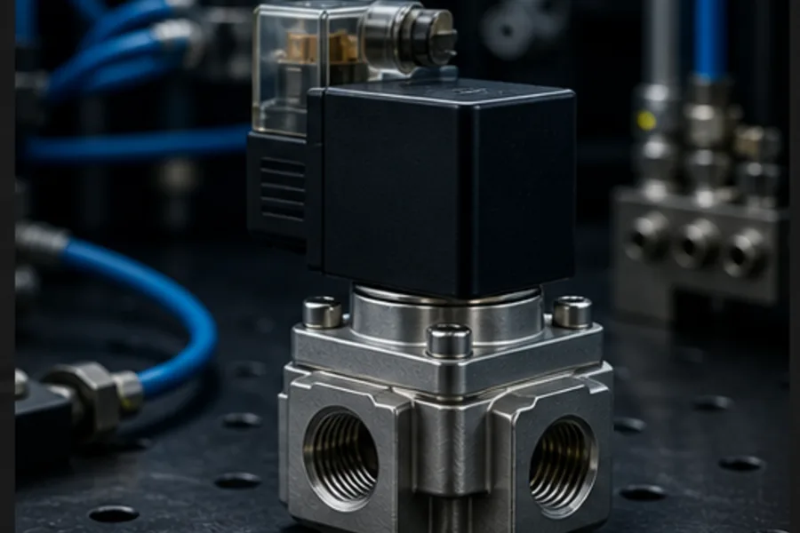
The important learning chain is PLC output → coil current → magnetic force → plunger/spool movement → flow path → cylinder or process response. If any link fails, the output LED can be on while nothing physical moves.
Direct-acting normally-closed valve
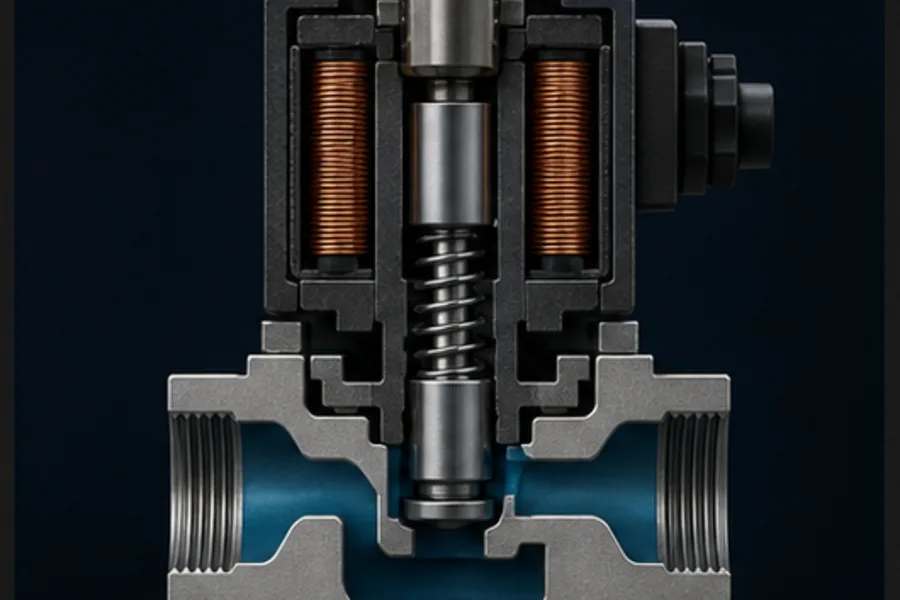
In the de-energised state, a spring pushes the plunger seal onto the valve seat. The inlet and outlet are isolated. This is the valve's normal state because the coil has no power.
When the coil is energised:
- Current produces a magnetic field around the coil.
- The magnetic circuit attracts the iron plunger.
- The plunger compresses the spring and lifts the seal.
- The inlet connects to the outlet.
- Flow begins if the pressure conditions permit it.
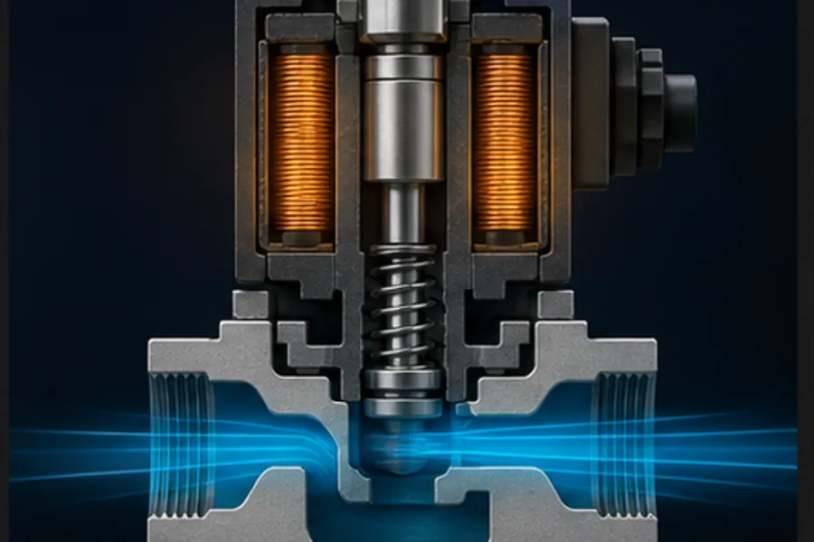
When power is removed, the magnetic force collapses and the return spring reseats the seal.
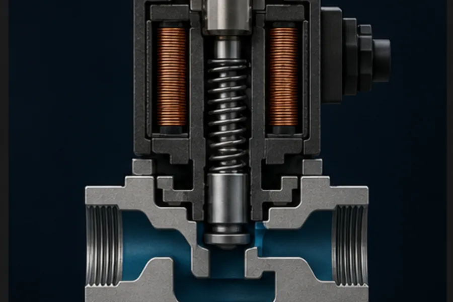
A normally-open version reverses the unpowered flow state. “Normally closed” describes fluid flow with the coil de-energised; it does not mean the electrical coil contact is NC.
Direct acting versus pilot operated
A direct-acting plunger must overcome spring force and fluid pressure across the seat. As valve orifice and pressure rise, the required magnetic force rises. This limits the practical flow size of a small coil.
A pilot-operated valve uses a small solenoid-operated pilot passage to create a pressure imbalance across a diaphragm or main piston. The process pressure supplies most of the force that opens the larger main path.
| Type | Main opening force | Important consequence |
|---|---|---|
| Direct acting | solenoid itself | can work from zero differential pressure; limited size/force |
| Internally piloted | process pressure assisted by pilot solenoid | higher flow from a small coil; often needs minimum pressure differential |
| Externally piloted | separate pilot supply | suitable where process pressure cannot operate the pilot reliably |
This explains a common field symptom: the coil clicks during a bench test, but the installed pilot valve will not pass flow because the inlet/outlet pressure condition is wrong.
What 2/2, 3/2 and 5/2 mean
Valve notation lists ports / positions:
- 2/2: two ports, two states; basic on/off isolation.
- 3/2: three ports, two states; supply/actuator/exhaust, common for single-acting cylinders.
- 5/2: five ports, two states; pressure, two cylinder ports and two exhausts, common for double-acting cylinders.
- 5/3: five ports, three states; adds a defined center condition such as closed, exhausted or pressurised center.
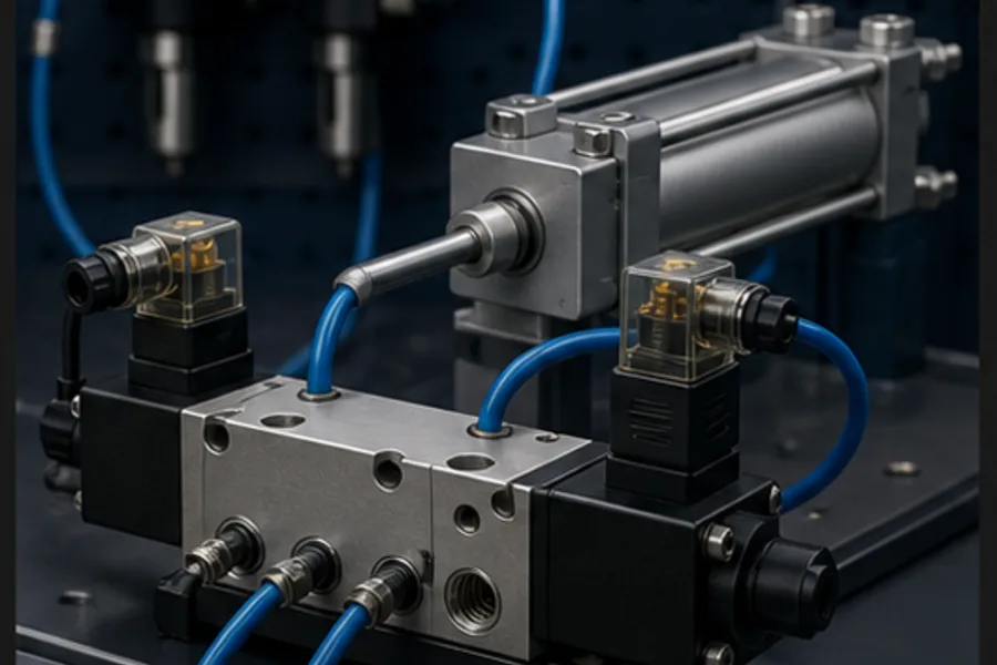
A 5/2 single-solenoid valve typically has a spring-return state. A double-solenoid valve can remain in its last state when both coils are off, depending on construction. That memory changes the machine's power-loss and restart behavior.
How a PLC output drives the coil
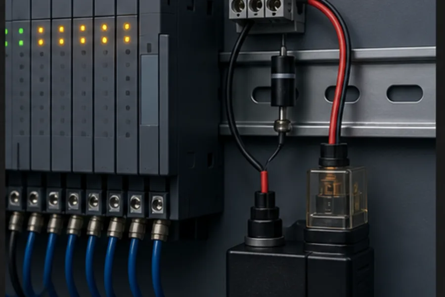
For a 24 VDC coil on a sourcing PLC output, the concept may be:
+24 V → PLC output group/common
PLC output Q0.2 → solenoid coil +
solenoid coil − → 0 V
A sinking module uses the opposite current path. Check the module diagram rather than guessing from conductor colour.
The coil is inductive. When current is interrupted, its magnetic field collapses and produces a voltage transient. Use the manufacturer-approved diode, TVS, RC or plug-in suppressor. A plain flyback diode is simple but can slow plunger release; that can matter in a fast or safety-related sequence.
Confirm:
- coil voltage and AC/DC type;
- steady and inrush current against output rating;
- output common/sourcing/sinking arrangement;
- suppression polarity and location;
- duty cycle and coil temperature; and
- manual override state.
Command, valve state and cylinder state are different
A robust PLC diagnostic distinguishes three facts:
- Command: the output bit is on.
- Valve actuation: spool/plunger actually changed state (some valves expose feedback).
- Process result: a pressure switch or cylinder limit confirms the expected motion.
If the PLC output is on but the cylinder does not extend, possibilities include an open coil, jammed spool, no air supply, low pilot pressure, blocked exhaust, incorrect porting, closed flow control, leaking cylinder seal or failed position sensor.
Use a proof timer based on realistic travel time. Too short creates nuisance faults; too long hides performance degradation.
Meter-out speed control and cushioning
For many pneumatic cylinders, stable speed is set by restricting exhaust (meter-out) rather than supply. Compressed air then maintains pressure on the driven side while exhaust restriction controls motion. End cushioning dissipates kinetic energy near stroke end; it does not fix an oversized load or excessive approach speed.
Valve flow capacity, tubing, fittings, silencers and exhaust restriction all affect cylinder speed. A large cylinder on a tiny valve will not achieve the catalog speed implied by bore and pressure alone.
Safe fault-finding sequence
Safety: compressed air stores energy and can create unexpected motion. Isolate electrical and pneumatic sources, exhaust trapped pressure and restrain gravity loads under the site's approved procedure.
- Read command, output LED and fault history without changing anything.
- Verify supply pressure and that the air-service/isolation arrangement is open.
- Confirm coil voltage at the valve connector while commanded.
- Listen/feel for actuation only if the safe procedure permits it.
- Check manual override is not latched.
- Verify port assignment and exhausts are not blocked.
- Separate valve failure from actuator/load failure by following approved test methods.
- Restore the normal state and reset diagnostics after the cause is removed.
Practise the internal flow path
The Solenoid Valve lesson shows the spring, coil, plunger and ports, then lets Pro learners energise the coil and watch the flow path change. Continue to the Pneumatic Cylinder lesson to see how a 5/2 valve turns that flow into extend/retract motion.
Frequently asked questions
What is a solenoid valve in plain English?
It is an electrically controlled tap or directional switch for air or liquid. An electromagnet moves an internal seal or spool when the PLC energises the coil.
What happens when a solenoid valve loses power?
A single-solenoid spring-return valve moves to its defined normal state. That may be open, closed, extend, retract or exhaust depending on the design. Never infer the safe state from coil count alone.
Why does a solenoid coil click but no air flows?
Possible causes include wrong porting, no supply, blocked exhaust, insufficient differential pressure for a pilot valve, a detached/damaged plunger, contaminated seat or a downstream restriction.
Can a PLC output power a solenoid directly?
Yes when coil voltage/current, output type, inrush, suppression and common wiring all match. Otherwise use a correctly rated interposing device or valve manifold interface.
What valve controls a double-acting cylinder?
A 5/2 directional valve is the common simple choice. It connects pressure to one cylinder chamber while exhausting the other, then swaps those paths for the reverse stroke.