PLC Simulator
PLC field notespneumatics

Pneumatic Cylinder Types & Selection

Compare single-acting, double-acting, rodless, guided and cushioned pneumatic cylinders by motion, force, air failure and PLC feedback.

PLC Simulation Software13 min read

Direct answer: Use a single-acting cylinder when air should drive one direction and a spring/gravity should define the return state. Use a double-acting cylinder when air must control force in both directions. Choose rodless, guided, compact, tandem or other designs when stroke, side load, space, rotation or force makes a standard rod cylinder unsuitable.
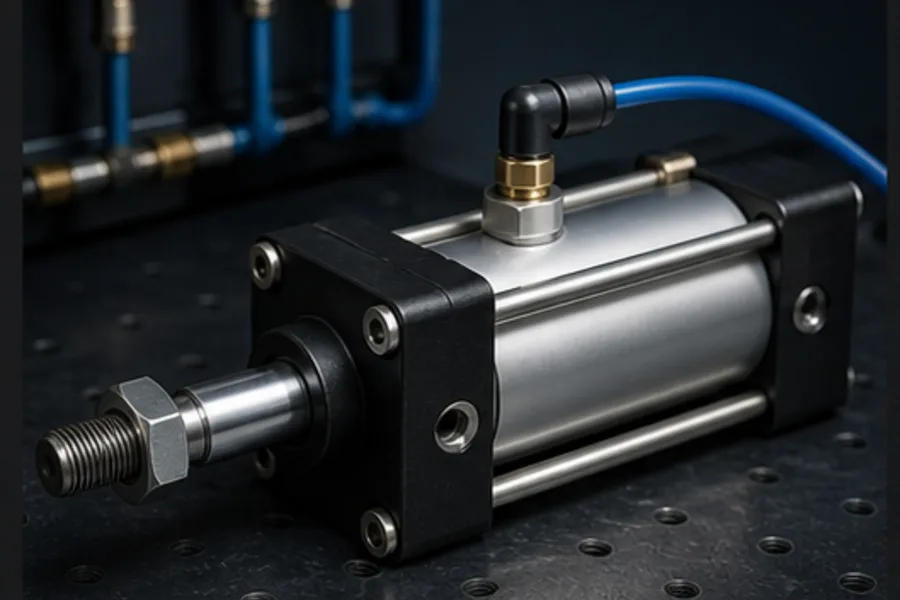
Double-acting pneumatic cylinder on an industrial training bench

All pneumatic cylinders convert pressure into linear force at a piston. The meaningful differences are how air reaches each chamber, how load is supported, what happens when air/power fails, and how the PLC proves position.

The basic force relationship

Approximate extension force is:

Force = pressure × effective piston area

Actual usable force is lower because of friction, pressure losses, seal condition, backpressure and design margin. Retraction force on a rod cylinder is lower because the rod occupies part of the piston area.

Never size a cylinder at exactly the theoretical load. Dynamic acceleration, orientation, binding, pressure variation and safe failure behavior matter.

Single-acting cylinder
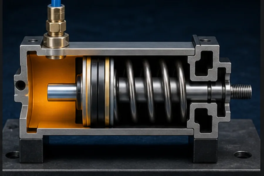
Single-acting pneumatic cylinder cutaway with one air port and spring return

A single-acting cylinder has one pressurised working port. Air moves the piston in one direction; a spring or external force returns it.

Advantages

  • defined spring-return position when air is removed;
  • one working air line and a simple 3/2 valve;
  • lower air use where work occurs only in one direction.

Limitations

  • spring occupies space and limits practical stroke;
  • available output force changes with spring compression;
  • powered force exists in only one direction;
  • exhaust/vent must remain clear.

Typical uses include ejecting, clamping, marking and light positioning where the return force is modest and a defined air-loss state is useful.

Double-acting cylinder
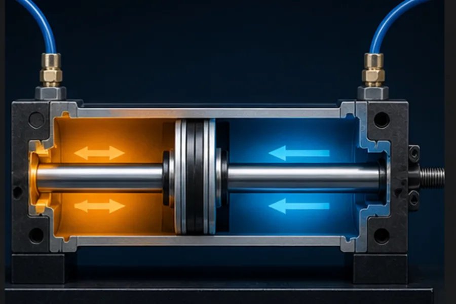
Double-acting cylinder cutaway with air alternately pressurising both piston faces

A double-acting cylinder has ports at both ends. A 5/2 valve sends pressure to one chamber while exhausting the other; shifting the valve reverses those paths.

Advantages

  • controlled powered motion in both directions;
  • long strokes and broad size range;
  • more consistent force than spring return;
  • independent extend/retract speed adjustment.

Limitations

  • consumes air for both movements;
  • air loss does not inherently define a safe position;
  • rod-side retraction force is lower;
  • load can move under gravity or external force if not restrained.

Festo identifies single-acting and double-acting cylinders as the two primary categories and notes the common 5/2 valve relationship for double-acting motion.

Rodless cylinder
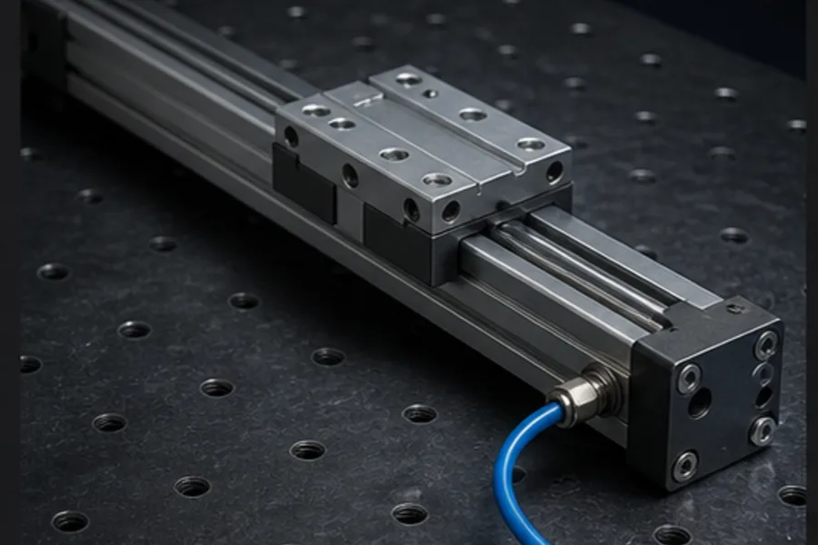
Rodless pneumatic cylinder moving a carriage along the actuator body

A rodless cylinder transfers piston motion to an external carriage without a rod extending beyond the barrel. Designs use a mechanical slot/seal or magnetic coupling.

Choose it when:

  • long stroke must fit in limited machine length;
  • the moving carriage should be supported along the actuator;
  • bending risk from a long extended rod is unacceptable.

Consider carriage loading, moment capacity, sealing, contamination and whether the load needs external guidance. A rodless actuator is not automatically a structural linear guide for every side load.

Guided cylinder / guided drive
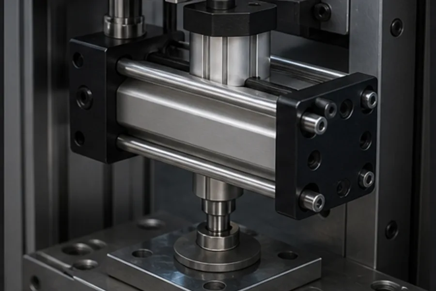
Guided pneumatic cylinder supporting a tooling load against side force and rotation

A guided cylinder combines the piston drive with guide rods/bearings so the tooling cannot rotate and side/moment loads are carried more effectively.

It is well suited to pressing, pick-and-place, stops and fixtures where a standard piston rod would bind or rotate. Check the manufacturer's load/moment charts for orientation and stroke; “guided” does not mean unlimited side load.

Compact, tandem, multi-position and rotary variants

Reference tableSwipe
TypeMain reason to choose it
Compact/short-strokelimited installation length
Tandemhigher force at the same bore/pressure by combining piston areas
Multi-positionseveral defined stroke positions without a servo axis
Through-rodmore balanced area/load support or motion at both ends
Locking/clampinghold position under defined loss-of-pressure conditions
Rotary actuatorconvert pneumatic energy to limited-angle rotation

Each adds constraints. A rod lock may hold a static load but is not automatically an emergency brake. Confirm its certified behavior for the exact risk.

Cushioning and end-of-stroke energy
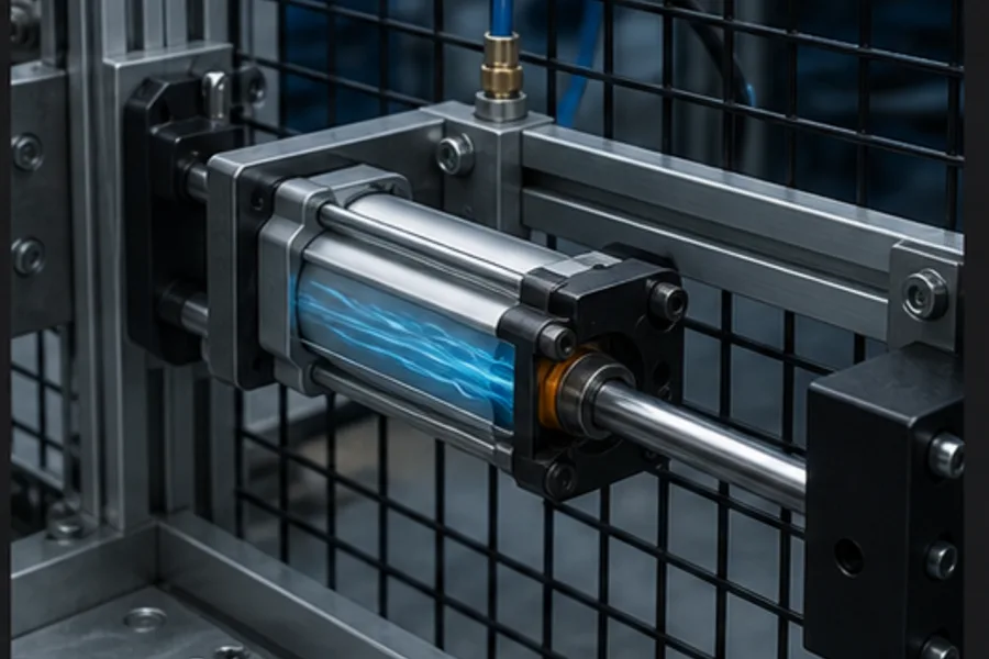
Cushioned pneumatic cylinder slowing before the end of its stroke in a guarded cell

End cushioning restricts exhaust near the end cap so the piston decelerates before impact. Adjustable pneumatic cushioning can be tuned for a load/speed range; elastomer bumpers handle smaller residual energy.

If a cylinder bangs at the end:

  1. reduce speed using correctly arranged flow control;
  2. verify load and pressure;
  3. adjust cushioning within the manufacturer's method;
  4. ensure exhaust is not causing unstable motion; and
  5. use an external shock absorber where kinetic energy requires it.

Cushioning cannot rescue a grossly undersized cylinder or uncontrolled falling load.

Meter-out flow control

Air's compressibility makes pneumatic motion prone to running away if only the inlet is restricted. In many horizontal/controlled applications, meter-out control restricts exhaust from the leaving chamber. Backpressure then stabilizes piston motion.

Place the flow controls at the cylinder ports as intended and orient one-way flow correctly. A reversed flow control is a common reason one direction is unexpectedly fast.

PLC sequence and feedback

A double-acting cylinder commonly exposes:

Reference tableSwipe
TagMeaning
CYL_EXTEND_CMDsolenoid command for extend path
CYL_RETRACT_CMDcommand for retract path, if double-solenoid
CYL_EXTENDEDend sensor proves extended position
CYL_RETRACTEDhome sensor proves retracted position

A safe sequence does not assume command equals position:

Command extend
→ start travel proof timer
→ wait for CYL_EXTENDED
→ if proof arrives, advance state
→ if timeout, remove/hold commands as designed and report EXTEND_TIMEOUT

Interlock opposing coils unless the valve specifically requires another strategy. On restart, determine actual position from sensors before continuing a sequence.

Choose from the required failure state

Ask what should happen if electrical power or air pressure disappears:

  • spring return to a defined state;
  • stop and remain trapped by a valve center condition;
  • exhaust to remove force;
  • hold with a mechanical lock/brake;
  • lower under controlled gravity; or
  • move to a safe state using stored energy.

There is no universally safest pneumatic state. Trapping air can hold a load but leave stored energy. Exhausting can remove force but allow gravity movement. The risk assessment determines the architecture.

Common faults by symptom

Reference tableSwipe
SymptomLikely checks
no movementsupply, valve command, manual override, pressure, jam
moves one direction onlyvalve/spool, blocked port/exhaust, seal, flow control
slow both wayslow pressure/flow, undersized valve/tube, high load, leakage
creepsvalve leakage, piston seal leakage, external load
chatters/stickscontamination, side load, low pressure, damaged guide
misses sensorsensor position, stopping energy, loose magnet/sensor, overspeed

Practise valve, cylinder and sensors as one system

The Pneumatic Cylinder lesson lets Pro learners switch between single- and double-acting behavior, route air, and observe position feedback. Pair it with the Solenoid Valve lesson before entering a pick-and-place scenario.

Frequently asked questions

What are the two main pneumatic cylinder types?

Single acting and double acting. Single acting uses air for one direction and spring/external force for return; double acting uses air for both directions.

What valve is used for a double-acting cylinder?

A 5/2 directional valve is the common choice. Five ports provide pressure, two actuator ports and two exhausts; two positions swap extend/retract flow paths.

Why is cylinder retraction force lower?

On the rod side, the piston rod subtracts from the effective pressure area. At the same pressure, the smaller annular area produces less theoretical force.

When should I use a rodless cylinder?

Use it when a long stroke must fit into a shorter installation envelope or a carriage arrangement is preferable. Confirm load/moment support and contamination requirements.

Can a pneumatic cylinder hold a suspended load after air loss?

Do not assume it can. Leakage, hose failure and valve center state can allow motion. Vertical loads may require a risk-assessed mechanical rod lock, brake, counterbalance or another technology.
Primary technical references

ShareX / TwitterLinkedIn

From reading to running logic

Route air through a working cylinder

Compare spring-return and double-acting motion, then prove end positions from the PLC side.

Open the cylinder lesson

Continue learning

Related field notes

All articles
pneumatics
solenoid valve

How a Solenoid Valve Works: Coil to Flow

See how direct and pilot solenoid valves move a plunger or spool, how NO/NC states work, and how a PLC output controls the coil.

12 min read
automation
plc

Industrial Automation Components Map

Understand PLCs, I/O, sensors, relays, drives, valves, safety and HMIs as one closed control loop—with interactive component labs.

15 min read
vfd
motor control

How a VFD Works: Rectifier to Motor

Follow power through a VFD from AC rectifier to DC bus and PWM inverter, then see how a PLC commands speed in an interactive motor lab.

13 min read

Technical reference and worked-example guide

Pneumatic cylinder types: implementation, evidence and troubleshooting

Direct answer

Pneumatic cylinder types becomes useful when it connects motion, force, stroke, orientation, side load, speed, duty, air quality, environment, valve and end-position evidence with plc command through solenoid valve, pressure and flow to piston motion, load movement and sensor feedback, then proves extend, hold, retract and loss-of-command behavior observed under a representative load under normal, boundary, fault and recovery conditions. The objective is a repeatable engineering or learning result, not merely activity inside a page or tool.

This guide is written for automation learners comparing single-acting, double-acting, guided, rodless, compact and rotary pneumatic actuators. The intended result is specific: the reader can connect actuator type, bore, stroke, load, speed, cushioning, valve and feedback to an observable machine requirement.

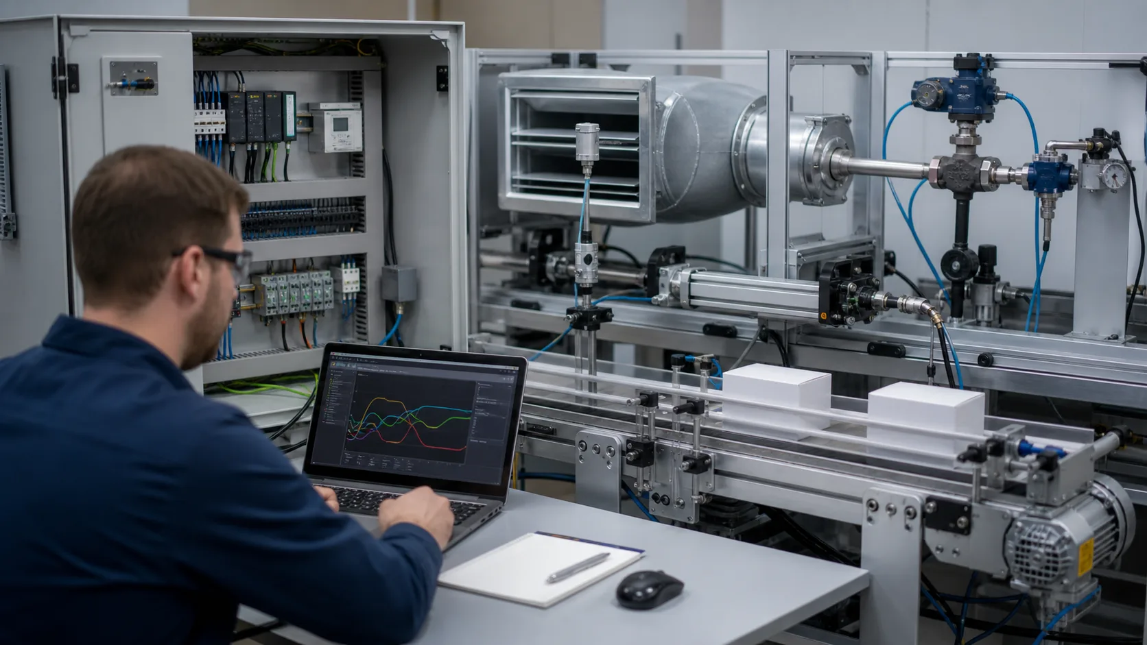
Engineer reviewing control trends beside an encoder, pneumatic actuator, HVAC duct and packaging conveyor used to study pneumatic actuator selection and PLC control
Use this physical system view to connect pneumatic actuator selection and PLC control with observable inputs, control decisions, outputs and verification evidence.

System map / 02

Six concepts that control the result

Treat these as connected checkpoints. Each checkpoint has an expected state, an observable state and a boundary to the next part of the system. That structure prevents a software indication from being mistaken for physical proof.

NODE 01observable

Define the operating contract

motion, force, stroke, orientation, side load, speed, duty, air quality, environment, valve and end-position evidence. For pneumatic actuator selection and PLC control, record the initial condition, actor, requested change, observable result and stopping condition before selecting a tool or implementation.

NODE 02observable

Map the evidence path

PLC command through solenoid valve, pressure and flow to piston motion, load movement and sensor feedback. Separate request, internal state, output or service, physical or user-visible result and independent feedback so each boundary can be inspected.

NODE 03observable

Prove normal operation

extend, hold, retract and loss-of-command behavior observed under a representative load. Run more than one cycle from a known state and retain the values, timings or artifacts that demonstrate repeatability.

NODE 04observable

Exercise a boundary case

low pressure, restricted exhaust, side load, leakage, cushioning, sticking, sensor shift and stored-energy restart. Choose minimum, maximum, simultaneous, delayed or restart conditions that reveal assumptions hidden by the happy path.

NODE 05observable

Diagnose a controlled fault

a command, valve, air, flow, actuator, mechanical-load or feedback defect. Preserve the first symptom, divide the system at a measurable boundary and change one condition only after predicting the result.

NODE 06observable

Transfer and hand over

selection and controls verified against manufacturer data and the machine risk assessment. Restore normal state, remove temporary changes, repeat affected checks and document which claims remain limited to the learning environment.

Procedure / 03

A six-step practice and commissioning workflow

Run the steps in order the first time. Later, the same structure becomes a diagnostic loop: define the expected condition, observe the boundary, interpret the difference and choose one proving action.

  1. 01

    Write the acceptance case

    Convert motion, force, stroke, orientation, side load, speed, duty, air quality, environment, valve and end-position evidence into initial conditions, one stimulus and observable pass criteria.

    Evidence: Another person can repeat the case without guessing the intended result.

    Avoid: Using page completion or an animation as the acceptance criterion.

  2. 02

    Build the map

    Document plc command through solenoid valve, pressure and flow to piston motion, load movement and sensor feedback and name who owns each state or decision.

    Evidence: Every request and result has a source, destination and useful inspection point.

    Avoid: Using the same value as command, status and independent feedback.

  3. 03

    Run the baseline

    Apply extend, hold, retract and loss-of-command behavior observed under a representative load from a clean start and record the expected evidence.

    Evidence: Repeated runs produce the same bounded result.

    Avoid: Changing several parameters before a baseline exists.

  4. 04

    Challenge assumptions

    Test low pressure, restricted exhaust, side load, leakage, cushioning, sticking, sensor shift and stored-energy restart without changing the acceptance contract.

    Evidence: Limits, timing and restart behavior reach defined states.

    Avoid: Testing only one ideal sequence.

  5. 05

    Isolate one failure

    Introduce or analyse a command, valve, air, flow, actuator, mechanical-load or feedback defect and locate the first disagreement.

    Evidence: The proving action distinguishes the leading hypotheses.

    Avoid: Resetting, forcing or replacing before evidence is retained.

  6. 06

    Close the evidence loop

    Complete selection and controls verified against manufacturer data and the machine risk assessment and repeat the affected regression cases.

    Evidence: Reference use is complete when inputs, assumptions, units or initial conditions are recorded and the result is independently checked at a useful boundary.

    Avoid: Treating an acknowledged message or one successful rerun as handover.

Diagnostic matrix / 04

Symptoms, proving points and next actions

The table is a reasoning aid, not a parts-replacement chart. Preserve the initial symptom, inspect the named boundary and use the interpretation to choose the next controlled test. Site safety procedures and equipment manuals remain authoritative.

Diagnostic symptoms, inspection points, interpretations and next actions for Pneumatic cylinder types: implementation, evidence and troubleshooting
Observed symptomInspectInterpretationNext proving action
The expected result is unclearRequirement, initial state, actor, stimulus, units and pass conditionThe technician, programmer and reviewer may be solving different versions of the task.Rewrite one observable acceptance case before continuing.
Internal state changes but the outcome does notRequest, final owner, output or service boundary and independent feedbackA software or interface indication proves intent at one layer, not the complete outcome.Trace the first boundary after the changing state.
Normal case passes but an edge case failsLimits, timing, simultaneous events, reset and restart assumptionsThe implementation contains a hidden assumption exposed by the changed condition.Add the failed boundary as a permanent regression case.
The failure disappears after resetOriginal symptom, histories, diagnostics, timestamps and active causeReset changed evidence or state without proving the initiating cause.Reproduce under a controlled condition and preserve pre/post-event data.
Simulator and target disagreeModel boundary, software version, task timing, I/O behavior, data types and configurationA learning model and the intended target do not share one of the recorded assumptions.Reduce the case and verify against current target documentation.
The result cannot be explainedPrediction, observation, proving action, alternative hypotheses and limitationsActivity occurred but the evidence is not yet transferable or reviewable.Have the learner defend the signal path and repeat a changed case.

Product evidence / 05

What the browser practice can actually demonstrate

The page connects definitions and worked examples to runnable tools, explicit assumptions and repeatable checks so a formula or pattern can be challenged.

Where simulation stops

The guide cannot size a safety-related actuator, validate stored-energy controls or replace manufacturer calculations and machine risk assessment.

Commissioning notebook / 06

Six cases that turn the concepts into evidence

Use these as written briefs rather than click-through instructions. For every case, state the expected condition before acting, retain the first useful observation and explain why the final result proves the requirement. A different program or component choice can still be correct when it produces the same bounded behavior and evidence.

Case 01

predict → observe → prove

Prove define the operating contract

Engineering context. motion, force, stroke, orientation, side load, speed, duty, air quality, environment, valve and end-position evidence. For pneumatic actuator selection and PLC control, record the initial condition, actor, requested change, observable result and stopping condition before selecting a tool or implementation. Begin with a written normal condition and identify which request, state, physical result or communication value will provide independent confirmation. Do not begin by changing the configuration; the initial state is part of the evidence and should remain reproducible.

Controlled setup. Use the “Write the acceptance case” stage of the workflow: convert motion, force, stroke, orientation, side load, speed, duty, air quality, environment, valve and end-position evidence into initial conditions, one stimulus and observable pass criteria. The acceptance record should show this result: another person can repeat the case without guessing the intended result. Record initial conditions, the exact stimulus and the observation point so another learner can repeat the case without relying on your memory.

Fault challenge. Introduce or analyse “The expected result is unclear” as one bounded deviation. Inspect requirement, initial state, actor, stimulus, units and pass condition The working interpretation is that the technician, programmer and reviewer may be solving different versions of the task. The next proving action is to rewrite one observable acceptance case before continuing. Change only one condition before observing the result, and preserve timestamps or measurements where timing matters.

Review and recovery. The most common trap here is using page completion or an animation as the acceptance criterion. After restoring the cause, repeat the normal case and at least one stop, timeout, disconnect or restart boundary relevant to this topic. Remove temporary forces and bypasses, return the model to a known state and retain the evidence that both operation and recovery are deliberate.

Explain it aloud: What should I learn first about pneumatic actuator selection and PLC control? A defensible short answer is: Start with the operating contract and evidence path: motion, force, stroke, orientation, side load, speed, duty, air quality, environment, valve and end-position evidence, followed by plc command through solenoid valve, pressure and flow to piston motion, load movement and sensor feedback. Add advanced features only after the baseline is predictable.

Case 02

predict → observe → prove

Prove map the evidence path

Engineering context. PLC command through solenoid valve, pressure and flow to piston motion, load movement and sensor feedback. Separate request, internal state, output or service, physical or user-visible result and independent feedback so each boundary can be inspected. Begin with a written normal condition and identify which request, state, physical result or communication value will provide independent confirmation. Do not begin by changing the configuration; the initial state is part of the evidence and should remain reproducible.

Controlled setup. Use the “Build the map” stage of the workflow: document plc command through solenoid valve, pressure and flow to piston motion, load movement and sensor feedback and name who owns each state or decision. The acceptance record should show this result: every request and result has a source, destination and useful inspection point. Record initial conditions, the exact stimulus and the observation point so another learner can repeat the case without relying on your memory.

Fault challenge. Introduce or analyse “Internal state changes but the outcome does not” as one bounded deviation. Inspect request, final owner, output or service boundary and independent feedback The working interpretation is that a software or interface indication proves intent at one layer, not the complete outcome. The next proving action is to trace the first boundary after the changing state. Change only one condition before observing the result, and preserve timestamps or measurements where timing matters.

Review and recovery. The most common trap here is using the same value as command, status and independent feedback. After restoring the cause, repeat the normal case and at least one stop, timeout, disconnect or restart boundary relevant to this topic. Remove temporary forces and bypasses, return the model to a known state and retain the evidence that both operation and recovery are deliberate.

Explain it aloud: How do I practise pneumatic actuator selection and PLC control effectively? A defensible short answer is: Use short cases with known initial conditions, a written prediction, one action and an observable result. Then alter a boundary or fault and explain why the evidence changed.

Case 03

predict → observe → prove

Prove prove normal operation

Engineering context. extend, hold, retract and loss-of-command behavior observed under a representative load. Run more than one cycle from a known state and retain the values, timings or artifacts that demonstrate repeatability. Begin with a written normal condition and identify which request, state, physical result or communication value will provide independent confirmation. Do not begin by changing the configuration; the initial state is part of the evidence and should remain reproducible.

Controlled setup. Use the “Run the baseline” stage of the workflow: apply extend, hold, retract and loss-of-command behavior observed under a representative load from a clean start and record the expected evidence. The acceptance record should show this result: repeated runs produce the same bounded result. Record initial conditions, the exact stimulus and the observation point so another learner can repeat the case without relying on your memory.

Fault challenge. Introduce or analyse “Normal case passes but an edge case fails” as one bounded deviation. Inspect limits, timing, simultaneous events, reset and restart assumptions The working interpretation is that the implementation contains a hidden assumption exposed by the changed condition. The next proving action is to add the failed boundary as a permanent regression case. Change only one condition before observing the result, and preserve timestamps or measurements where timing matters.

Review and recovery. The most common trap here is changing several parameters before a baseline exists. After restoring the cause, repeat the normal case and at least one stop, timeout, disconnect or restart boundary relevant to this topic. Remove temporary forces and bypasses, return the model to a known state and retain the evidence that both operation and recovery are deliberate.

Explain it aloud: What counts as proof of competence? A defensible short answer is: A repeatable artifact or system result plus an explanation of the signal path is stronger than time spent, screenshots or a copied answer. Physical competence requires separate supervised evidence.

Case 04

predict → observe → prove

Prove exercise a boundary case

Engineering context. low pressure, restricted exhaust, side load, leakage, cushioning, sticking, sensor shift and stored-energy restart. Choose minimum, maximum, simultaneous, delayed or restart conditions that reveal assumptions hidden by the happy path. Begin with a written normal condition and identify which request, state, physical result or communication value will provide independent confirmation. Do not begin by changing the configuration; the initial state is part of the evidence and should remain reproducible.

Controlled setup. Use the “Challenge assumptions” stage of the workflow: test low pressure, restricted exhaust, side load, leakage, cushioning, sticking, sensor shift and stored-energy restart without changing the acceptance contract. The acceptance record should show this result: limits, timing and restart behavior reach defined states. Record initial conditions, the exact stimulus and the observation point so another learner can repeat the case without relying on your memory.

Fault challenge. Introduce or analyse “The failure disappears after reset” as one bounded deviation. Inspect original symptom, histories, diagnostics, timestamps and active cause The working interpretation is that reset changed evidence or state without proving the initiating cause. The next proving action is to reproduce under a controlled condition and preserve pre/post-event data. Change only one condition before observing the result, and preserve timestamps or measurements where timing matters.

Review and recovery. The most common trap here is testing only one ideal sequence. After restoring the cause, repeat the normal case and at least one stop, timeout, disconnect or restart boundary relevant to this topic. Remove temporary forces and bypasses, return the model to a known state and retain the evidence that both operation and recovery are deliberate.

Explain it aloud: Why test faults and restart behavior? A defensible short answer is: Because a command, valve, air, flow, actuator, mechanical-load or feedback defect or low pressure, restricted exhaust, side load, leakage, cushioning, sticking, sensor shift and stored-energy restart can expose assumptions that never appear during ideal startup and steady operation.

Case 05

predict → observe → prove

Prove diagnose a controlled fault

Engineering context. a command, valve, air, flow, actuator, mechanical-load or feedback defect. Preserve the first symptom, divide the system at a measurable boundary and change one condition only after predicting the result. Begin with a written normal condition and identify which request, state, physical result or communication value will provide independent confirmation. Do not begin by changing the configuration; the initial state is part of the evidence and should remain reproducible.

Controlled setup. Use the “Isolate one failure” stage of the workflow: introduce or analyse a command, valve, air, flow, actuator, mechanical-load or feedback defect and locate the first disagreement. The acceptance record should show this result: the proving action distinguishes the leading hypotheses. Record initial conditions, the exact stimulus and the observation point so another learner can repeat the case without relying on your memory.

Fault challenge. Introduce or analyse “Simulator and target disagree” as one bounded deviation. Inspect model boundary, software version, task timing, I/O behavior, data types and configuration The working interpretation is that a learning model and the intended target do not share one of the recorded assumptions. The next proving action is to reduce the case and verify against current target documentation. Change only one condition before observing the result, and preserve timestamps or measurements where timing matters.

Review and recovery. The most common trap here is resetting, forcing or replacing before evidence is retained. After restoring the cause, repeat the normal case and at least one stop, timeout, disconnect or restart boundary relevant to this topic. Remove temporary forces and bypasses, return the model to a known state and retain the evidence that both operation and recovery are deliberate.

Explain it aloud: Can browser practice replace official software or hardware? A defensible short answer is: No. It can build concepts and diagnostic reasoning. Exact firmware, I/O electrical behavior, networking, safety and commissioning require current official tools, documentation and target equipment.

Case 06

predict → observe → prove

Prove transfer and hand over

Engineering context. selection and controls verified against manufacturer data and the machine risk assessment. Restore normal state, remove temporary changes, repeat affected checks and document which claims remain limited to the learning environment. Begin with a written normal condition and identify which request, state, physical result or communication value will provide independent confirmation. Do not begin by changing the configuration; the initial state is part of the evidence and should remain reproducible.

Controlled setup. Use the “Close the evidence loop” stage of the workflow: complete selection and controls verified against manufacturer data and the machine risk assessment and repeat the affected regression cases. The acceptance record should show this result: reference use is complete when inputs, assumptions, units or initial conditions are recorded and the result is independently checked at a useful boundary. Record initial conditions, the exact stimulus and the observation point so another learner can repeat the case without relying on your memory.

Fault challenge. Introduce or analyse “The result cannot be explained” as one bounded deviation. Inspect prediction, observation, proving action, alternative hypotheses and limitations The working interpretation is that activity occurred but the evidence is not yet transferable or reviewable. The next proving action is to have the learner defend the signal path and repeat a changed case. Change only one condition before observing the result, and preserve timestamps or measurements where timing matters.

Review and recovery. The most common trap here is treating an acknowledged message or one successful rerun as handover. After restoring the cause, repeat the normal case and at least one stop, timeout, disconnect or restart boundary relevant to this topic. Remove temporary forces and bypasses, return the model to a known state and retain the evidence that both operation and recovery are deliberate.

Explain it aloud: How should progress be documented? A defensible short answer is: Keep the requirement, initial state, program or configuration, observed values, fault hypothesis, proving action, recovery result and a concise limitations statement.

Answer surface / 07

Questions people ask about Pneumatic cylinder types

These concise answers define the operating, training and product boundaries most often missed in broad summaries. The full workflow and diagnostic table above provide the evidence behind them.

What should I learn first about pneumatic actuator selection and PLC control?

Start with the operating contract and evidence path: motion, force, stroke, orientation, side load, speed, duty, air quality, environment, valve and end-position evidence, followed by plc command through solenoid valve, pressure and flow to piston motion, load movement and sensor feedback. Add advanced features only after the baseline is predictable.

How do I practise pneumatic actuator selection and PLC control effectively?

Use short cases with known initial conditions, a written prediction, one action and an observable result. Then alter a boundary or fault and explain why the evidence changed.

What counts as proof of competence?

A repeatable artifact or system result plus an explanation of the signal path is stronger than time spent, screenshots or a copied answer. Physical competence requires separate supervised evidence.

Why test faults and restart behavior?

Because a command, valve, air, flow, actuator, mechanical-load or feedback defect or low pressure, restricted exhaust, side load, leakage, cushioning, sticking, sensor shift and stored-energy restart can expose assumptions that never appear during ideal startup and steady operation.

Can browser practice replace official software or hardware?

No. It can build concepts and diagnostic reasoning. Exact firmware, I/O electrical behavior, networking, safety and commissioning require current official tools, documentation and target equipment.

How should progress be documented?

Keep the requirement, initial state, program or configuration, observed values, fault hypothesis, proving action, recovery result and a concise limitations statement.

What should I do when the answer differs from a guide?

Check assumptions, version, units and initial state first. Reduce the case, compare one boundary at a time and prefer current primary documentation for target-specific behavior.

When is a pneumatic actuator selection and PLC control exercise finished?

Reference use is complete when inputs, assumptions, units or initial conditions are recorded and the result is independently checked at a useful boundary.