
PLC Simulator
Free + runnable

PLC Practice Problems: Ladder Logic Exercises With a Live In-Browser Simulator

Every problem is runnable. Write the ladder, press Run, and get instant pass/fail feedback — just like a real PLC scan cycle. No install, no hardware, no static diagrams.

Join 9000+ learners practicing PLC programming

Real PLC practice problems footage

See this exact skill in the working simulator.

Watch the real browser product respond to the task on this page, then try the same practical workflow yourself. No slides, concept mockups, install, or credit card.

Try this in the browser
Your First PLC Program — Switch Turns On a Light

Practise the full reasoning loop

From a first rung to unseen fault states

The problems should become harder in the same dimensions as real control work: more state, more time, more interaction between devices, and less certainty about where the fault lives.

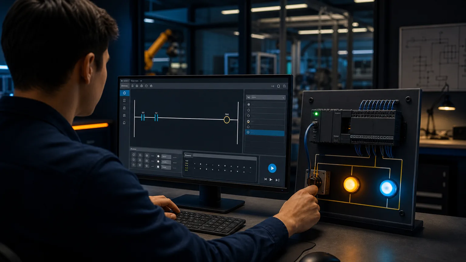
PLC learner building a first ladder rung in a browser while a physical switch and light training panel responds
01Begin with one visible cause-and-effect loop: build the rung, run it, operate the input and observe the output.
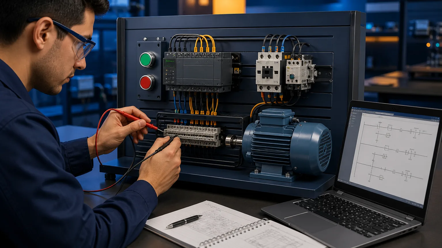
Motor start stop PLC practice bench with pushbuttons, contactor, overload, motor and ladder logic laptop
02Connect the PLC command to contactor, overload and motor behavior instead of treating the rung as an isolated drawing.
PLC timer ladder exercise controlling a tabletop conveyor after an on-delay interval
03Use a timer problem to distinguish the enable condition, accumulated time and done state from the output it controls.
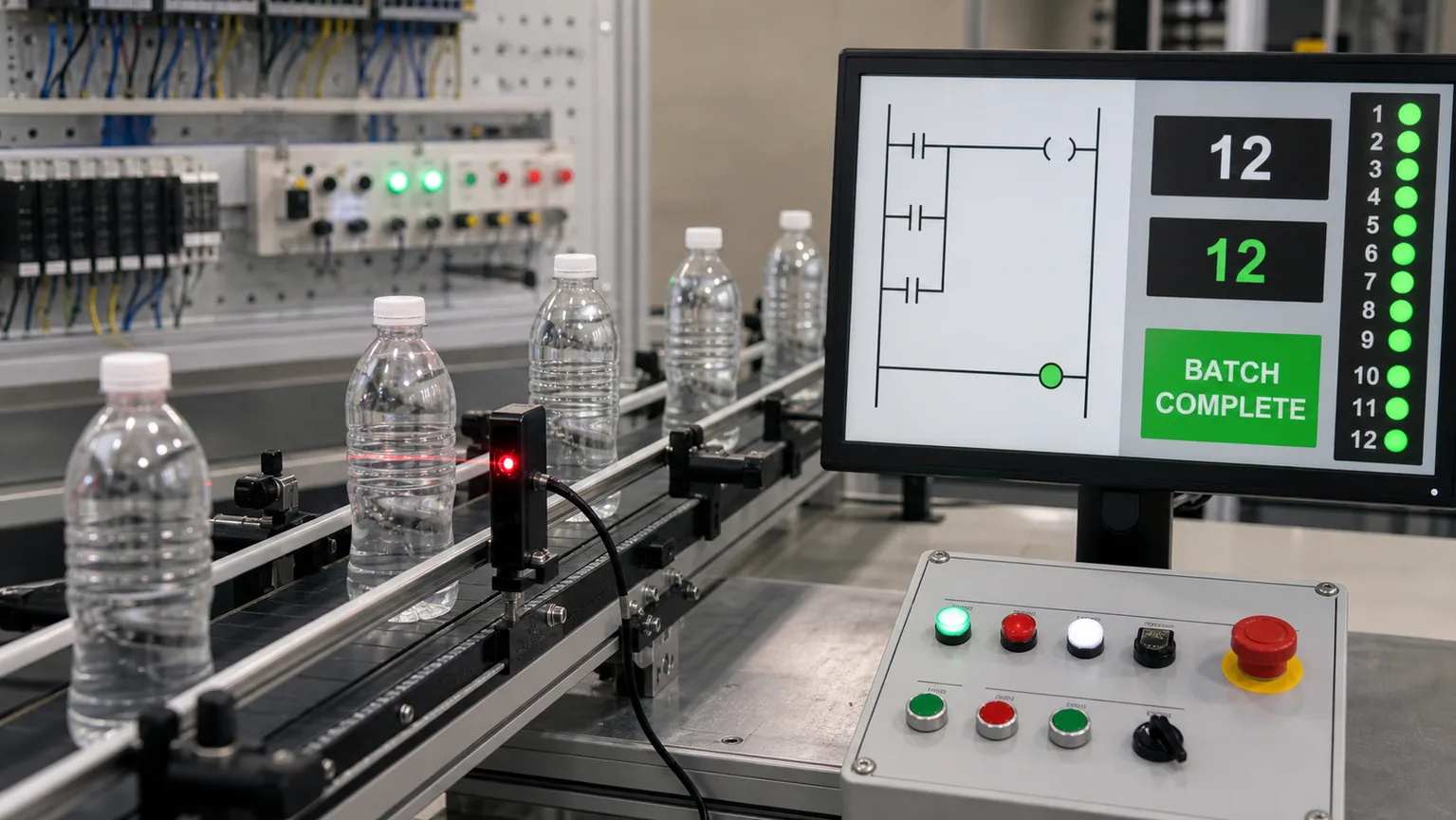
Bottle conveyor PLC counter exercise with photoelectric sensor and completed batch indication
04Count events on signal edges, stop at the preset and prove the reset behavior with another batch.
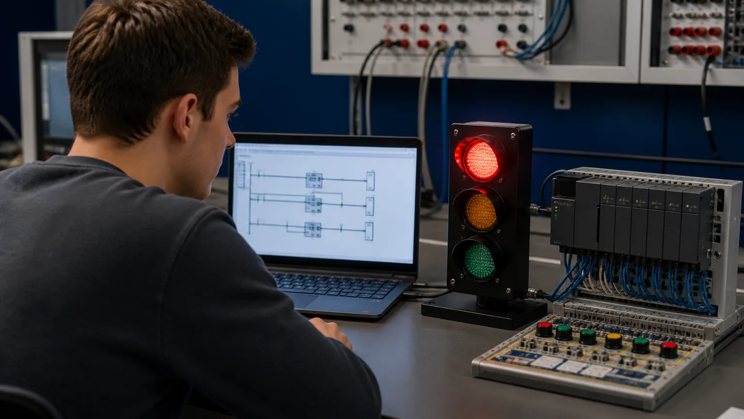
PLC traffic light sequencing exercise with staged timers and a three-color signal
05Intermediate practice introduces mutually exclusive states, timed transitions and deterministic cycle restart.
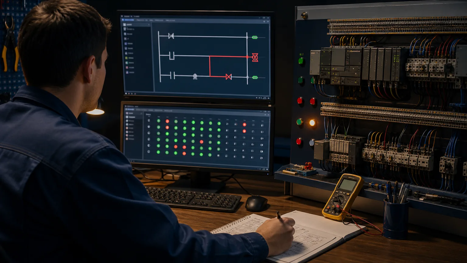
Controls learner diagnosing a highlighted ladder fault from simulated I/O and objective test indicators
06Use the exact failing input state to isolate one incorrect rung, make the smallest fix and rerun the checks.

The problem with static resources

Why static PLC practice problems miss the point

Search for "PLC practice problems" and you will find dozens of PDF worksheets and blog posts. They share the same format: a machine description, a hand-drawn rung diagram, and an answer at the bottom. Read the problem, look at the solution, feel like you understand it. Move to the next one.

The problem is that reading a correct rung diagram is nothing like writing one. When you sit down at a real PLC — or a job-site laptop running Studio 5000 — you have a blank rung and a machine that needs to do something. Nobody hands you the answer. You have to build it, run it, and figure out why the motor sealed in when it should not have.

That feedback loop — build, execute, observe, fix — is the actual skill. Static practice problems train reading comprehension. This platform trains programming.

Each listed guided exercise opens a live scenario. You write ladder logic in a visual editor, the platform executes the simulated PLC scan cycle, applies the test states defined for that exercise, and reports which checks pass or fail. The grader is not checking that your diagram merely looks right. It is checking that the program behaves as the exercise requires.

That is the difference: build it, run it, grade it.

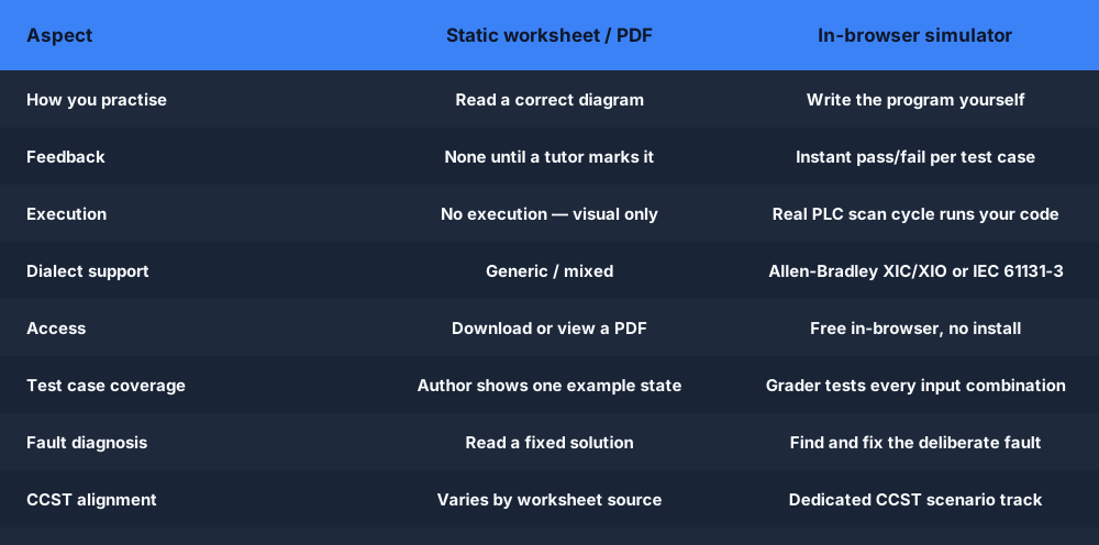
static PLC practice problems versus interactive runnable ladder logic exercises
Static practice problems train recognition. Interactive exercises train the build-run-fix loop that real PLC work requires.

Build it

Use the visual ladder editor to place contacts and coils. The instruction set mirrors Allen-Bradley (XIC, XIO, OTE, TON, CTU) or IEC 61131-3, switchable per scenario.

Run it

Press Run and the platform executes your program against a simulated I/O table through every test case. No install, no external software, no hardware.

Grade it

Each test case reports pass or fail. You see exactly which input combination broke your logic so you can fix the rung rather than guess.

Beginner ladder logic exercises

Free beginner PLC practice problems

These four problems cover basic discrete control, the seal-in latch, timer-controlled sequences and event counting. The anonymous /try program comes first; the catalog exercises below require a free account so progress and grades can be saved. No credit card is required for the free tier.

Beginner
Free account

Motor Start/Stop

Wire a Start and Stop button to control a motor output. No latch — the motor only runs while Start is held.

What to build:

One XIC Start contact, one XIO Stop contact, one OTE Motor coil.

Open this practice problem →
Beginner
Free account

Seal-In Latch

Add a seal-in branch so the motor holds itself on after Start is released.

What to build:

A parallel Motor XIC contact sealing around the Start button. Classic three-wire control.

Open this practice problem →
Beginner
Free account

TON Timer Sequence

Start the motor, then automatically stop it after 5 seconds using a TON on-delay timer.

What to build:

One TON with preset 5000 ms. Motor.DN contact opens the motor rung when the timer fires.

Open this practice problem →
Beginner
Free account

Counter — Bottle Passes

Count 10 bottles on a conveyor using a CTU instruction and stop the line when the batch is complete.

What to build:

CTU with preset 10. A Sensor XIC pulses the count input on each rising edge. QU bit stops the conveyor.

Open this practice problem →

Problem 1 detail: Motor Start/Stop

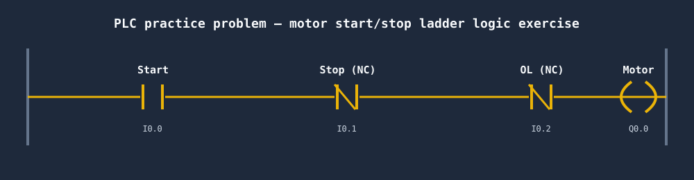
The motor start/stop circuit is the "hello world" of PLC programming. A normally-open Start contact in series with a normally-closed Stop contact drives a Motor output coil. When Start is momentarily pressed, the output energises — but only for as long as the button is held, because there is no latch. The next problem adds the seal-in branch that makes this circuit behave like a real motor control circuit.

This problem teaches you to read a problem statement, identify the inputs and outputs, assign I/O addresses, and place the correct contact types. It sounds simple — it trips up many beginners because the Stop contact must be normally-closed (fail-safe), not normally-open.

PLC practice problem motor start stop ladder logic exercise
The motor start/stop rung — the foundation problem every PLC learner must build first.
Seal-in latch PLC practice problem — a parallel motor holding contact seals around the start button so the motor holds on after start is releasedA seal-in latch rung: a Start contact in parallel with a Hold contact, in series with a normally-closed Stop contact, driving an output coil.StartHold (seal)StopMotor
Problem 2 adds the seal-in branch: a parallel Motor contact holds the rung true after the Start button is released — the latch that turns this into real three-wire control.

Problem 3 detail: TON Timer Sequence

Timers appear in the majority of real PLC programs: motor run-up delays, conveyor hold times, recipe step durations, alarm annunciation delays. The TON (on-delay timer) is the most common. It starts timing when the enable rung goes true, accumulates time in milliseconds, and sets its Done bit when the accumulated time reaches the preset.

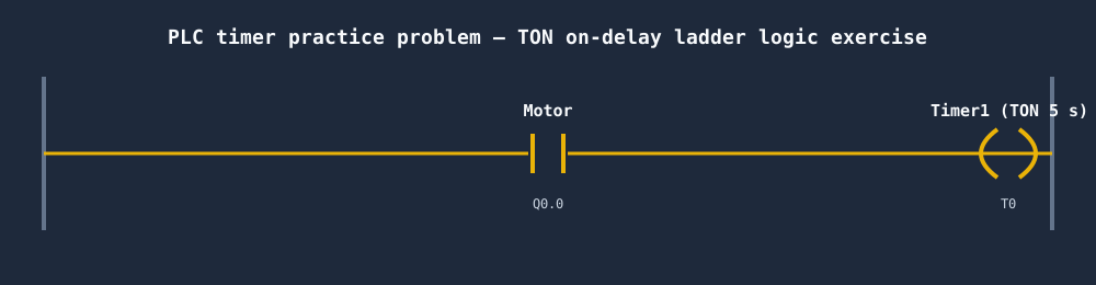
In this problem, the Motor starts on a seal-in rung (from Problem 2), then a TON begins timing from the moment the Motor output energises. When the timer's Done bit fires after 5 seconds, it breaks the Motor rung. This teaches the key pattern: using an output coil address as the enable for a timer, and using the timer's Done bit to trigger the next action.

PLC timer practice problem TON ladder logic exercise
TON timer practice problem — the Motor rung enables the timer, the Done bit breaks the Motor rung after 5 seconds.
CTU counter PLC practice problem — counting ten bottles on a conveyor and stopping the line when the accumulated count reaches the presetA CTU count-up counter: each input pulse increments the accumulator toward the preset, and the done (DN) bit turns on when count reaches preset.count pulsesCTUPRE 5ACC 3ACCcount toward presetDNdone bit
Problem 4 is the CTU counter: each rising edge of the sensor increments the count; the done bit (QU) stops the conveyor when the batch of ten is complete.
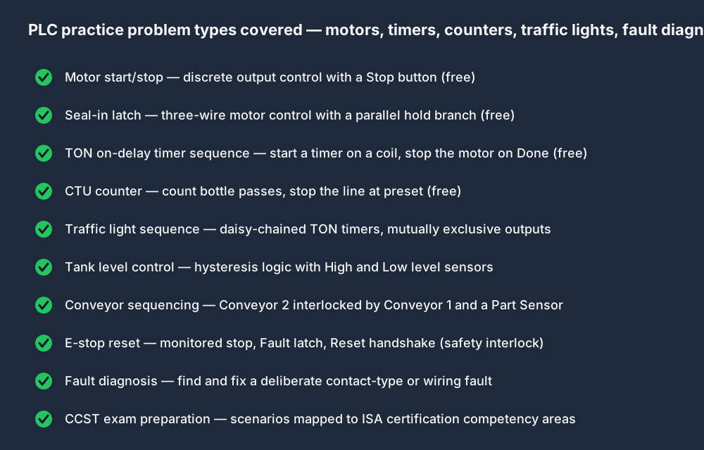
PLC practice problems covered motors timers counters traffic lights faults
Practice problem types available — from basic discrete control to fault diagnosis and CCST exam prep.

Intermediate ladder logic exercises

Intermediate PLC practice problems

Once you can write a motor seal-in and a TON sequence without referring to notes, these problems introduce multi-step sequencing, interlocks, level control, and safety circuits. These are the problem types that appear in entry-level PLC technician interviews. Intermediate problems require a Pro account for graded access, but you can read the problem statement and attempt them on a free account.

Intermediate
Pro

Traffic Light Sequence

Implement a timed green/amber/red traffic light cycle using TON timers and sequential step bits.

What to build:

Three TON timers daisy-chained so each done bit activates the next phase. Reset at the end of the cycle.

View this scenario →
Intermediate
Pro

Tank Level Control

Control a fill valve and drain pump based on high and low level sensor inputs with hysteresis.

What to build:

Low-level XIC opens the fill valve; High-level XIO holds it open. High-level NC contact enables the drain pump.

View this scenario →
Intermediate
Pro

Conveyor Sequencing

Drive two conveyors in sequence: Conveyor 2 only runs while Conveyor 1 is running and a part is detected.

What to build:

Interlock rungs. Conveyor 1 seal-in. Conveyor 2 gated by Conveyor 1 and Part Sensor contacts in series.

View this scenario →
Intermediate
Pro

Fault Detection and E-Stop

Implement a monitored E-stop with a reset handshake — the machine cannot restart without an operator reset after an E-stop event.

What to build:

E-stop XIO in series with every output rung. A latched Fault bit blocks restart until the Reset button is pressed.

View this scenario →

Traffic light sequence — deep dive

The traffic light problem is a classic sequencing exercise because the solution forces you to think about mutually exclusive states and timed transitions. A naive approach uses a single timer and bitwise output logic. A better approach uses three separate TON timers daisy-chained: the green timer's Done bit enables the amber timer, the amber timer's Done bit enables the red timer, and the red timer's Done bit resets everything and restarts the green timer.

The key insight is that only one output can be on at a time — if your logic ever turns two outputs on simultaneously, the program is wrong even if the timing is right. The auto-grader tests this explicitly with cross-checks on all output combinations.

E-stop and fault detection — why this problem matters

Safety interlocks are not optional in real industrial systems — they are a regulatory requirement. The E-stop reset problem teaches the monitored stop pattern: the E-stop contact is wired normally-closed in series with every output rung (so a broken wire is a safe stop, not a stuck-on condition). A separate Fault latch captures the stop event. The machine cannot restart until an operator presses a Reset button while the E-stop is clear.

This pattern teaches a core distinction between a healthy-state permissive and a deliberate reset. In real machinery, the safety function belongs in validated safety hardware or a safety PLC; the standard controller can monitor status and sequence recovery but should not replace the required safety architecture.

Fault diagnosis — the most underrated practice type

Most PLC practice problem resources focus on writing programs. Real PLC technicians spend the majority of their time reading programs that someone else wrote and finding out why a machine stopped. The fault diagnosis problems on this platform give you a pre-written ladder program with a deliberate fault — a normally-closed contact that should be normally-open, a timer preset that is too short, a missing seal-in branch. You have to identify the fault, fix it, and confirm the fix by running the grader.

Assessment

PLC practice test — assess your skills

Practice problems build skills; a structured practice test reveals gaps. The platform offers timed assessment scenarios that combine multiple-choice questions about instruction behaviour with rung interpretation and live coding exercises. Completing a practice test tells you exactly which topic areas to revisit before a job interview or certification exam.

Multiple-choice questions

Questions about instruction behaviour, contact types, timer and counter mechanics, and scan-cycle order. Use these to reveal knowledge gaps, not as replicas of any certification exam.

Rung interpretation

Given a ladder rung and an I/O state, predict the output. This tests whether you can trace logic mentally — a skill every PLC technician needs at the control panel.

Live graded exercises

Write a ladder program that satisfies a set of requirements. The grader runs your program against the full test suite and scores it. Timed to simulate interview conditions.

How grading works

When you submit a ladder program, the grader builds an I/O truth table from the problem specification. It then runs your program through every row of that table: applying the input combination, executing the scan cycle, and comparing your output values to the expected values. A program that produces the correct output on 8 of 10 test cases scores 80%, and you see exactly which two cases failed.

This is harder to fool than most online exercises. You cannot write a program that turns every output on and "pass" — the grader tests combinations where specific outputs must be off. You cannot hardcode a single answer — the grader varies the inputs systematically. The only way to score 100% is to write logic that correctly handles all conditions.

For CCST study support, the platform includes scenarios informed by public control-systems competency areas such as basic ladder logic, timer and counter applications, analog I/O concepts and safety-interlock reasoning. They are independent practice, not official ISA exam questions or a score predictor.

Allen-Bradley dialect

Allen-Bradley PLC practice problems

Allen-Bradley (Rockwell Automation) PLCs — ControlLogix, CompactLogix, MicroLogix — hold the largest market share in North American manufacturing. RSLogix 5000 and its successor Studio 5000 use a specific set of instruction mnemonics that differ from the IEC 61131-3 names: the normally-open contact is XIC (Examine If Closed), the normally-closed contact is XIO (Examine If Open), the standard output coil is OTE (Output Energise), and latching/unlatching instructions are OTL and OTU.

Practising with generic ladder logic diagrams does not prepare you for Studio 5000. You need to build muscle memory for the AB instruction names and the tag-based addressing model (Motor, not %Q0.0 or Q0.0 — symbolic tags like MotorRun, Timer1.DN, Counter1.ACC).

Every practice problem on this platform can be solved in Allen-Bradley dialect. Toggle the dialect selector on any scenario to switch to AB mode. The editor uses XIC, XIO, OTE, OTL, OTU, TON, CTU — the exact instruction names you will see in Studio 5000. The timer and counter member syntax (.DN, .EN, .ACC, .PRE) matches the Allen-Bradley convention.

Practising in AB dialect is also the fastest way to prepare for a job that requires RSLogix experience. You get the instruction-name recognition without needing a Studio 5000 licence (which runs several hundred dollars per seat per year) or a ControlLogix rack (which runs thousands of dollars for a training setup).

Allen-Bradley ladder logic symbol reference for PLC practice problems — XIC examine-if-closed, XIO examine-if-open, OTE output energise, OTL and OTU latch and unlatch, TON timer and CTU counterThe core ladder logic symbols side by side: XIC examine-if-closed, XIO examine-if-open, OTE output energize, OTL output latch and OTU output unlatch.XICIfXIOIfOTEEnergizeLOTLLatchUOTUUnlatch
The Allen-Bradley instruction set you place in every AB-dialect problem: XIC, XIO, OTE, OTL/OTU, TON, CTU — the exact mnemonics Studio 5000 and RSLogix use.

Motor Start/Stop (AB)

XIC Start, XIO Stop, OTE Motor — the seal-in rung in Allen-Bradley dialect.

Open scenario →

Start/Stop No Latch (AB)

Verify you understand the difference between a momentary and a latching circuit in AB syntax.

Open scenario →

Latch Start (AB)

Add the OTL / seal-in branch. The motor holds itself in after Start is released.

Open scenario →

TON Delay Sequence (AB)

AB-style TON: Timer1.EN, Timer1.DN, Timer1.ACC — the member naming that Studio 5000 uses.

Open scenario →

E-Stop Reset (AB)

OTL Fault latch, XIO E-Stop NC, XIC Reset — safety interlock in AB dialect.

Open scenario →

Fault Diagnosis (AB)

A pre-written AB program with a contact-type fault. Find it, fix it, pass the grader.

Open scenario →

Allen-Bradley, Rockwell Automation, Studio 5000, RSLogix, ControlLogix, CompactLogix, and MicroLogix are registered trademarks of Rockwell Automation, Inc. This site is not affiliated with or endorsed by Rockwell Automation, Inc.

Problem-solving technique

Tips for getting unstuck on a PLC practice problem

Read the I/O list before you draw a rung

Every problem statement includes an input/output table. Before touching the editor, write out your tag assignments on paper. Knowing that I0.0 is the Start PB (normally-open momentary) and I0.1 is the Stop PB (normally-closed) prevents you from placing the wrong contact type — the single most common beginner error.

Think in conditions, not instructions

Ask "what condition must be true for this output to turn on?" not "what instruction do I put here?" If the Motor output should be on whenever the Start button was pressed AND the Stop has not been pressed AND the overload has not tripped, write those three conditions in plain language. Converting each condition to a contact type is then mechanical.

Trace the scan cycle mentally

Before running the grader, simulate one scan in your head: inputs update the I/O table, the processor evaluates your rungs left-to-right top-to-bottom, outputs are written. What is the state of each output after one scan if Start is pressed? If Stop is pressed? If both are pressed? If you can answer these without running the program, you will catch most bugs before the grader sees them.

When a test case fails, trace that specific case

The grader shows which simulated input condition failed. Recreate that state in the I/O panel and trace the rungs one at a time. Find the rung producing the wrong output, make the smallest justified fix, and rerun the checks.

NC contact on Stop is almost always the answer

If your motor-control circuit fails the "Stop pressed" test case, your Stop contact is probably normally-open (XIC) instead of normally-closed (XIO). This is the most common mistake in motor-control problems. Normally-closed contacts on Stop and Overload inputs are a safety requirement — the circuit fails safe on a broken wire.

Timers need an enable rung, not a constant power rail

A TON timer only accumulates time while its enable rung is continuously TRUE. If you connect the TON directly to the power rail, it will count to its preset on the first scan and immediately fire its Done bit. The enable rung should be the condition that starts the timing — usually a coil address or a sensor contact. When the enable rung goes FALSE, the ACC resets to zero (for a TON).

How to read a PLC practice problem statement

Most problem statements are written in the style of a machine specification: "The motor shall start when the Start button is pressed and remain running until the Stop button is pressed or the overload trips." This is not a rung diagram — it is a behavioural specification that you need to translate into logic.

Underline the verbs: start when pressed, remain running, stop when pressed. Each verb-phrase maps to a rung or a contact type. "Start when pressed" means a normally-open contact. "Remain running" means a seal-in parallel branch. "Stop when pressed" means a normally-closed contact in series.

Look for the word "unless" or "except" — these indicate interlocks that must appear as normally-closed contacts in series with the output rung. "The motor shall run unless the overload has tripped" translates to an XIO Overload contact in series.

Look for "after" or "delay" — these indicate timers. "The motor shall stop after 30 seconds" translates to a TON with a 30,000 ms preset whose Done bit opens the motor rung. Look for "count" or "batch" — these indicate CTU counters.

PLC scan cycle for practice problems — read inputs, execute the ladder program top to bottom, then update outputs, repeating every scanThe repeating PLC scan cycle: read inputs, execute the ladder logic, update outputs, then housekeeping, looping continuously.1Read Inputs2Execute Logic3Update Outputs4HousekeepingSCANCYCLE
Trace one scan in your head before you run the grader: inputs are read, your rungs evaluate top-to-bottom left-to-right, then outputs are written. Most logic bugs are visible from a single mental scan.
PLC troubleshooting flow for practice problems — confirm the fault, recreate the failing simulated input state, isolate the rung, fix, and rerun the graderA PLC fault-diagnosis flow from top to bottom: observe the symptom, check the inputs, check the logic, check the outputs, then apply the fix.SymptomCheck inputsCheck logicCheck outputsFix
Fault-diagnosis problems train this loop: read the failing test case, recreate that exact input combination, isolate the wrong rung, fix only that rung, re-run.
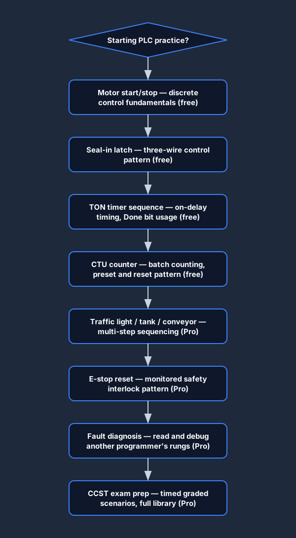
PLC practice exercises progression beginner to advanced
Skill progression: discrete control → timer sequences → counter batching → sequencing → fault diagnosis → CCST prep.

Building toward a CCST certificate?

The ISA Certified Control Systems Technician (CCST) exam covers PLC programming, discrete and analog I/O, instrumentation, and safety systems. The graded scenarios on this platform include a dedicated CCST track with problems modelled on the competency areas the exam tests. Completing the CCST track problems before your exam gives you confidence in your ability to write and interpret ladder logic under timed conditions.

The CCST track includes motor control, timer and counter applications, analog scaling concepts, and E-stop/safety interlock patterns — the same topics the ISA study guide emphasises. Scores on the auto-graded scenarios give you a directional signal about which areas need more practice before exam day.

How to solve a PLC practice problem on this platform

01

Read the problem

Understand the machine: what inputs exist, what outputs are required, and what behavioural conditions the problem specifies.

02

Assign I/O

Map the inputs and outputs to the I/O table provided. Identify which contacts should be normally-open and which should be normally-closed.

03

Build the rungs

Use the visual ladder editor to place contacts and coils. Add branches, timer blocks, and counter blocks as the problem requires.

04

Run the scan

Press Run. The platform executes your program against the simulated I/O through every test case in the grader.

05

Check the grade

Review which test cases passed and which failed. Trace the failing case to the specific rung and fix it. Repeat until 100%.

Why practice here vs a static worksheet

Instant grading — know in seconds whether your logic is correct, not after marking by a tutor
Test-case transparency — see exactly which input state broke your program, not just a total score
Real execution — your ladder runs a genuine scan cycle, not a visual check of diagram appearance
Allen-Bradley dialect — practice XIC/XIO/OTE/TON/CTU so the Studio 5000 names feel natural
No install required — browser-based, works on Mac, Windows, Linux, Chromebook
CCST alignment — graded scenarios mapped to ISA certification competency areas
FAQ

PLC practice problems — frequently asked questions

Start with the no-account guided Switch & Light program, then use a free account for motor start/stop, a TON on-delay timer and a CTU counter. Those exercises build from discrete logic to state, time and events. The free tier currently includes 27 source-tagged scenario records; availability can vary with staged rollout.

Building toward a certificate? See our free PLC training →

Build your skills — start practising now

Run the guided first problem without an account. Create a free account for saved catalog practice; Pro unlocks the wider graded library and advanced learning support.

Competency and practice field guide

PLC practice problems: implementation, evidence and troubleshooting

Direct answer

PLC practice problems becomes useful when it connects learner level, prerequisite, target instruction, process model, i/o, initial state, acceptance criteria, boundary case, allowed evidence and review method with problem statement through i/o contract, logic design, scan execution, modeled response, test result, diagnosis and retained explanation, then proves one discrete, timer, counter, sequence or analog problem completed from a clean state without revealing a copied solution under normal, boundary, fault and recovery conditions. The objective is a repeatable engineering or learning result, not merely activity inside a page or tool.

This guide is written for pLC beginners, technicians and instructors choosing independent exercises for contacts, latches, timers, counters, sequences, analog signals and diagnostics. The intended result is specific: the learner can select a problem by competency, translate its brief into testable behavior and prove the result against normal, boundary and changed cases.
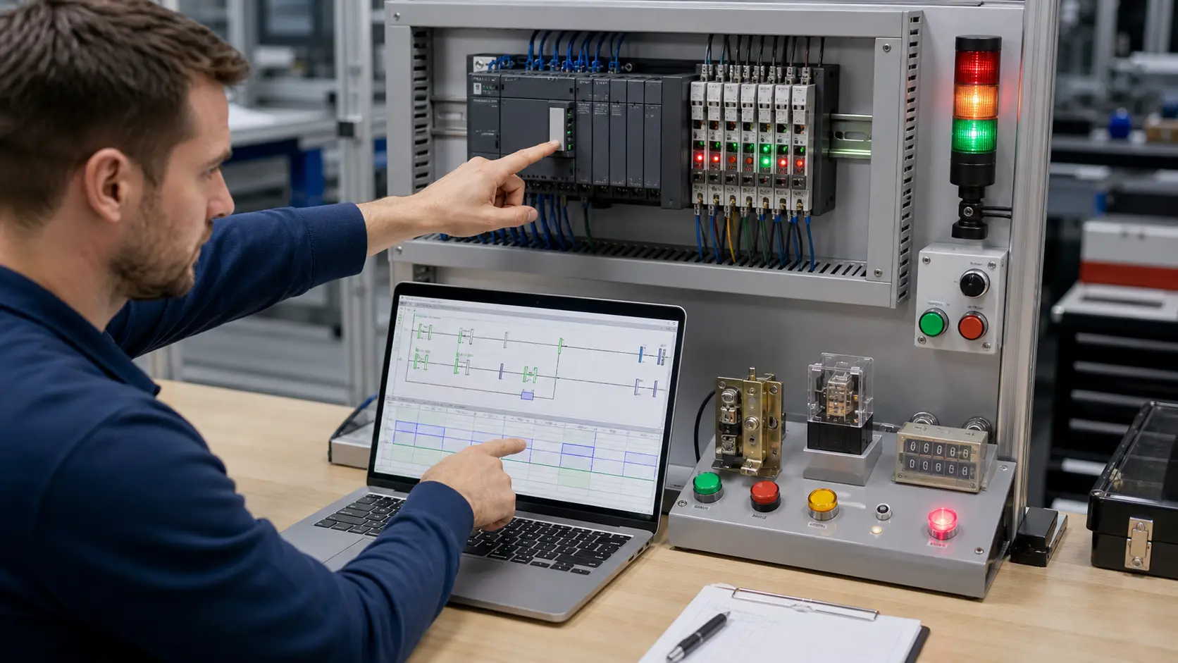
an automation engineer correlating ladder logic, scan timing, PLC I/O and a controlled test result at a debug bench while studying progressive PLC programming problems with observable acceptance evidence
The physical context keeps progressive PLC programming problems with observable acceptance evidence tied to declared inputs, owned decisions, observable results and evidence that another person can verify.

System map / 02

Six concepts that control the result

Treat these as connected checkpoints. Each checkpoint has an expected state, an observable state and a boundary to the next part of the system. That structure prevents a software indication from being mistaken for physical proof.

NODE 01observable

Define the operating contract

learner level, prerequisite, target instruction, process model, I/O, initial state, acceptance criteria, boundary case, allowed evidence and review method. For progressive PLC programming problems with observable acceptance evidence, record the initial condition, actor, requested change, observable result and stopping condition before selecting a tool or implementation.

NODE 02observable

Map the evidence path

problem statement through I/O contract, logic design, scan execution, modeled response, test result, diagnosis and retained explanation. Separate request, internal state, output or service, physical or user-visible result and independent feedback so each boundary can be inspected.

NODE 03observable

Prove normal operation

one discrete, timer, counter, sequence or analog problem completed from a clean state without revealing a copied solution. Run more than one cycle from a known state and retain the values, timings or artifacts that demonstrate repeatability.

NODE 04observable

Exercise a boundary case

simultaneous commands, held input, exact timer boundary, count edge, reset, power return, sensor fault and changed process condition. Choose minimum, maximum, simultaneous, delayed or restart conditions that reveal assumptions hidden by the happy path.

NODE 05observable

Diagnose a controlled fault

a requirement, I/O, Boolean, state, timing, count, sequence, scaling or diagnostic error. Preserve the first symptom, divide the system at a measurable boundary and change one condition only after predicting the result.

NODE 06observable

Transfer and hand over

the solution varied, regression-tested and then recreated in the intended vendor environment under appropriate supervision. Restore normal state, remove temporary changes, repeat affected checks and document which claims remain limited to the learning environment.

Procedure / 03

A six-step practice and commissioning workflow

Run the steps in order the first time. Later, the same structure becomes a diagnostic loop: define the expected condition, observe the boundary, interpret the difference and choose one proving action.

  1. 01

    Write the acceptance case

    Convert learner level, prerequisite, target instruction, process model, i/o, initial state, acceptance criteria, boundary case, allowed evidence and review method into initial conditions, one stimulus and observable pass criteria.

    Evidence: Another person can repeat the case without guessing the intended result.

    Avoid: Using page completion or an animation as the acceptance criterion.

  2. 02

    Build the map

    Document problem statement through i/o contract, logic design, scan execution, modeled response, test result, diagnosis and retained explanation and name who owns each state or decision.

    Evidence: Every request and result has a source, destination and useful inspection point.

    Avoid: Using the same value as command, status and independent feedback.

  3. 03

    Run the baseline

    Apply one discrete, timer, counter, sequence or analog problem completed from a clean state without revealing a copied solution from a clean start and record the expected evidence.

    Evidence: Repeated runs produce the same bounded result.

    Avoid: Changing several parameters before a baseline exists.

  4. 04

    Challenge assumptions

    Test simultaneous commands, held input, exact timer boundary, count edge, reset, power return, sensor fault and changed process condition without changing the acceptance contract.

    Evidence: Limits, timing and restart behavior reach defined states.

    Avoid: Testing only one ideal sequence.

  5. 05

    Isolate one failure

    Introduce or analyse a requirement, i/o, boolean, state, timing, count, sequence, scaling or diagnostic error and locate the first disagreement.

    Evidence: The proving action distinguishes the leading hypotheses.

    Avoid: Resetting, forcing or replacing before evidence is retained.

  6. 06

    Close the evidence loop

    Complete the solution varied, regression-tested and then recreated in the intended vendor environment under appropriate supervision and repeat the affected regression cases.

    Evidence: A learner completes the surface by explaining the result, passing a changed case and identifying what still requires supervised target-equipment practice.

    Avoid: Treating an acknowledged message or one successful rerun as handover.

Diagnostic matrix / 04

Symptoms, proving points and next actions

The table is a reasoning aid, not a parts-replacement chart. Preserve the initial symptom, inspect the named boundary and use the interpretation to choose the next controlled test. Site safety procedures and equipment manuals remain authoritative.

Diagnostic symptoms, inspection points, interpretations and next actions for PLC practice problems: implementation, evidence and troubleshooting
Observed symptomInspectInterpretationNext proving action
The expected result is unclearRequirement, initial state, actor, stimulus, units and pass conditionThe learner, instructor and assessor may be solving different versions of the task.Rewrite one observable acceptance case before continuing.
Internal state changes but the outcome does notRequest, final owner, output or service boundary and independent feedbackA software or interface indication proves intent at one layer, not the complete outcome.Trace the first boundary after the changing state.
Normal case passes but an edge case failsLimits, timing, simultaneous events, reset and restart assumptionsThe implementation contains a hidden assumption exposed by the changed condition.Add the failed boundary as a permanent regression case.
The failure disappears after resetOriginal symptom, histories, diagnostics, timestamps and active causeReset changed evidence or state without proving the initiating cause.Reproduce under a controlled condition and preserve pre/post-event data.
Simulator and target disagreeModel boundary, software version, task timing, I/O behavior, data types and configurationA learning model and the intended target do not share one of the recorded assumptions.Reduce the case and verify against current target documentation.
The result cannot be explainedPrediction, observation, proving action, alternative hypotheses and limitationsActivity occurred but the evidence is not yet transferable or reviewable.Have the learner defend the signal path and repeat a changed case.

Product evidence / 05

What the browser practice can actually demonstrate

The browser platform can retain programs, scenario results, attempts and observable machine state so practice is attached to evidence rather than seat time alone.

Where simulation stops

Practice problems measure only the published simulated behaviors and do not replace target-platform, electrical, safety or supervised commissioning assessment.

Commissioning notebook / 06

Six cases that turn the concepts into evidence

Use these as written briefs rather than click-through instructions. For every case, state the expected condition before acting, retain the first useful observation and explain why the final result proves the requirement. A different program or component choice can still be correct when it produces the same bounded behavior and evidence.

Case 01

predict → observe → prove

Prove define the operating contract

Engineering context. learner level, prerequisite, target instruction, process model, I/O, initial state, acceptance criteria, boundary case, allowed evidence and review method. For progressive PLC programming problems with observable acceptance evidence, record the initial condition, actor, requested change, observable result and stopping condition before selecting a tool or implementation. Begin with a written normal condition and identify which request, state, physical result or communication value will provide independent confirmation. Do not begin by changing the configuration; the initial state is part of the evidence and should remain reproducible.

Controlled setup. Use the “Write the acceptance case” stage of the workflow: convert learner level, prerequisite, target instruction, process model, i/o, initial state, acceptance criteria, boundary case, allowed evidence and review method into initial conditions, one stimulus and observable pass criteria. The acceptance record should show this result: another person can repeat the case without guessing the intended result. Record initial conditions, the exact stimulus and the observation point so another learner can repeat the case without relying on your memory.

Fault challenge. Introduce or analyse “The expected result is unclear” as one bounded deviation. Inspect requirement, initial state, actor, stimulus, units and pass condition The working interpretation is that the learner, instructor and assessor may be solving different versions of the task. The next proving action is to rewrite one observable acceptance case before continuing. Change only one condition before observing the result, and preserve timestamps or measurements where timing matters.

Review and recovery. The most common trap here is using page completion or an animation as the acceptance criterion. After restoring the cause, repeat the normal case and at least one stop, timeout, disconnect or restart boundary relevant to this topic. Remove temporary forces and bypasses, return the model to a known state and retain the evidence that both operation and recovery are deliberate.

Explain it aloud: What PLC practice problems should a beginner solve first? A defensible short answer is: Start with input-to-output truth, stop-priority start-stop, seal-in state, timers and counters, then progress to sequences, analog scaling and fault diagnosis.

Case 02

predict → observe → prove

Prove map the evidence path

Engineering context. problem statement through I/O contract, logic design, scan execution, modeled response, test result, diagnosis and retained explanation. Separate request, internal state, output or service, physical or user-visible result and independent feedback so each boundary can be inspected. Begin with a written normal condition and identify which request, state, physical result or communication value will provide independent confirmation. Do not begin by changing the configuration; the initial state is part of the evidence and should remain reproducible.

Controlled setup. Use the “Build the map” stage of the workflow: document problem statement through i/o contract, logic design, scan execution, modeled response, test result, diagnosis and retained explanation and name who owns each state or decision. The acceptance record should show this result: every request and result has a source, destination and useful inspection point. Record initial conditions, the exact stimulus and the observation point so another learner can repeat the case without relying on your memory.

Fault challenge. Introduce or analyse “Internal state changes but the outcome does not” as one bounded deviation. Inspect request, final owner, output or service boundary and independent feedback The working interpretation is that a software or interface indication proves intent at one layer, not the complete outcome. The next proving action is to trace the first boundary after the changing state. Change only one condition before observing the result, and preserve timestamps or measurements where timing matters.

Review and recovery. The most common trap here is using the same value as command, status and independent feedback. After restoring the cause, repeat the normal case and at least one stop, timeout, disconnect or restart boundary relevant to this topic. Remove temporary forces and bypasses, return the model to a known state and retain the evidence that both operation and recovery are deliberate.

Explain it aloud: How do I know whether a PLC exercise is solved correctly? A defensible short answer is: Write observable acceptance cases before programming, then test normal operation, exact boundaries, simultaneous inputs, reset and a changed or faulted condition.

Case 03

predict → observe → prove

Prove prove normal operation

Engineering context. one discrete, timer, counter, sequence or analog problem completed from a clean state without revealing a copied solution. Run more than one cycle from a known state and retain the values, timings or artifacts that demonstrate repeatability. Begin with a written normal condition and identify which request, state, physical result or communication value will provide independent confirmation. Do not begin by changing the configuration; the initial state is part of the evidence and should remain reproducible.

Controlled setup. Use the “Run the baseline” stage of the workflow: apply one discrete, timer, counter, sequence or analog problem completed from a clean state without revealing a copied solution from a clean start and record the expected evidence. The acceptance record should show this result: repeated runs produce the same bounded result. Record initial conditions, the exact stimulus and the observation point so another learner can repeat the case without relying on your memory.

Fault challenge. Introduce or analyse “Normal case passes but an edge case fails” as one bounded deviation. Inspect limits, timing, simultaneous events, reset and restart assumptions The working interpretation is that the implementation contains a hidden assumption exposed by the changed condition. The next proving action is to add the failed boundary as a permanent regression case. Change only one condition before observing the result, and preserve timestamps or measurements where timing matters.

Review and recovery. The most common trap here is changing several parameters before a baseline exists. After restoring the cause, repeat the normal case and at least one stop, timeout, disconnect or restart boundary relevant to this topic. Remove temporary forces and bypasses, return the model to a known state and retain the evidence that both operation and recovery are deliberate.

Explain it aloud: What should I learn first about progressive PLC programming problems with observable acceptance evidence? A defensible short answer is: Start with the operating contract and evidence path: learner level, prerequisite, target instruction, process model, i/o, initial state, acceptance criteria, boundary case, allowed evidence and review method, followed by problem statement through i/o contract, logic design, scan execution, modeled response, test result, diagnosis and retained explanation. Add advanced features only after the baseline is predictable.

Case 04

predict → observe → prove

Prove exercise a boundary case

Engineering context. simultaneous commands, held input, exact timer boundary, count edge, reset, power return, sensor fault and changed process condition. Choose minimum, maximum, simultaneous, delayed or restart conditions that reveal assumptions hidden by the happy path. Begin with a written normal condition and identify which request, state, physical result or communication value will provide independent confirmation. Do not begin by changing the configuration; the initial state is part of the evidence and should remain reproducible.

Controlled setup. Use the “Challenge assumptions” stage of the workflow: test simultaneous commands, held input, exact timer boundary, count edge, reset, power return, sensor fault and changed process condition without changing the acceptance contract. The acceptance record should show this result: limits, timing and restart behavior reach defined states. Record initial conditions, the exact stimulus and the observation point so another learner can repeat the case without relying on your memory.

Fault challenge. Introduce or analyse “The failure disappears after reset” as one bounded deviation. Inspect original symptom, histories, diagnostics, timestamps and active cause The working interpretation is that reset changed evidence or state without proving the initiating cause. The next proving action is to reproduce under a controlled condition and preserve pre/post-event data. Change only one condition before observing the result, and preserve timestamps or measurements where timing matters.

Review and recovery. The most common trap here is testing only one ideal sequence. After restoring the cause, repeat the normal case and at least one stop, timeout, disconnect or restart boundary relevant to this topic. Remove temporary forces and bypasses, return the model to a known state and retain the evidence that both operation and recovery are deliberate.

Explain it aloud: How do I practise progressive PLC programming problems with observable acceptance evidence effectively? A defensible short answer is: Use short cases with known initial conditions, a written prediction, one action and an observable result. Then alter a boundary or fault and explain why the evidence changed.

Case 05

predict → observe → prove

Prove diagnose a controlled fault

Engineering context. a requirement, I/O, Boolean, state, timing, count, sequence, scaling or diagnostic error. Preserve the first symptom, divide the system at a measurable boundary and change one condition only after predicting the result. Begin with a written normal condition and identify which request, state, physical result or communication value will provide independent confirmation. Do not begin by changing the configuration; the initial state is part of the evidence and should remain reproducible.

Controlled setup. Use the “Isolate one failure” stage of the workflow: introduce or analyse a requirement, i/o, boolean, state, timing, count, sequence, scaling or diagnostic error and locate the first disagreement. The acceptance record should show this result: the proving action distinguishes the leading hypotheses. Record initial conditions, the exact stimulus and the observation point so another learner can repeat the case without relying on your memory.

Fault challenge. Introduce or analyse “Simulator and target disagree” as one bounded deviation. Inspect model boundary, software version, task timing, I/O behavior, data types and configuration The working interpretation is that a learning model and the intended target do not share one of the recorded assumptions. The next proving action is to reduce the case and verify against current target documentation. Change only one condition before observing the result, and preserve timestamps or measurements where timing matters.

Review and recovery. The most common trap here is resetting, forcing or replacing before evidence is retained. After restoring the cause, repeat the normal case and at least one stop, timeout, disconnect or restart boundary relevant to this topic. Remove temporary forces and bypasses, return the model to a known state and retain the evidence that both operation and recovery are deliberate.

Explain it aloud: What counts as proof of competence? A defensible short answer is: A repeatable artifact or system result plus an explanation of the signal path is stronger than time spent, screenshots or a copied answer. Physical competence requires separate supervised evidence.

Case 06

predict → observe → prove

Prove transfer and hand over

Engineering context. the solution varied, regression-tested and then recreated in the intended vendor environment under appropriate supervision. Restore normal state, remove temporary changes, repeat affected checks and document which claims remain limited to the learning environment. Begin with a written normal condition and identify which request, state, physical result or communication value will provide independent confirmation. Do not begin by changing the configuration; the initial state is part of the evidence and should remain reproducible.

Controlled setup. Use the “Close the evidence loop” stage of the workflow: complete the solution varied, regression-tested and then recreated in the intended vendor environment under appropriate supervision and repeat the affected regression cases. The acceptance record should show this result: a learner completes the surface by explaining the result, passing a changed case and identifying what still requires supervised target-equipment practice. Record initial conditions, the exact stimulus and the observation point so another learner can repeat the case without relying on your memory.

Fault challenge. Introduce or analyse “The result cannot be explained” as one bounded deviation. Inspect prediction, observation, proving action, alternative hypotheses and limitations The working interpretation is that activity occurred but the evidence is not yet transferable or reviewable. The next proving action is to have the learner defend the signal path and repeat a changed case. Change only one condition before observing the result, and preserve timestamps or measurements where timing matters.

Review and recovery. The most common trap here is treating an acknowledged message or one successful rerun as handover. After restoring the cause, repeat the normal case and at least one stop, timeout, disconnect or restart boundary relevant to this topic. Remove temporary forces and bypasses, return the model to a known state and retain the evidence that both operation and recovery are deliberate.

Explain it aloud: Why test faults and restart behavior? A defensible short answer is: Because a requirement, i/o, boolean, state, timing, count, sequence, scaling or diagnostic error or simultaneous commands, held input, exact timer boundary, count edge, reset, power return, sensor fault and changed process condition can expose assumptions that never appear during ideal startup and steady operation.

Answer surface / 07

Questions people ask about PLC practice problems

These concise answers define the operating, training and product boundaries most often missed in broad summaries. The full workflow and diagnostic table above provide the evidence behind them.

What PLC practice problems should a beginner solve first?

Start with input-to-output truth, stop-priority start-stop, seal-in state, timers and counters, then progress to sequences, analog scaling and fault diagnosis.

How do I know whether a PLC exercise is solved correctly?

Write observable acceptance cases before programming, then test normal operation, exact boundaries, simultaneous inputs, reset and a changed or faulted condition.

What should I learn first about progressive PLC programming problems with observable acceptance evidence?

Start with the operating contract and evidence path: learner level, prerequisite, target instruction, process model, i/o, initial state, acceptance criteria, boundary case, allowed evidence and review method, followed by problem statement through i/o contract, logic design, scan execution, modeled response, test result, diagnosis and retained explanation. Add advanced features only after the baseline is predictable.

How do I practise progressive PLC programming problems with observable acceptance evidence effectively?

Use short cases with known initial conditions, a written prediction, one action and an observable result. Then alter a boundary or fault and explain why the evidence changed.

What counts as proof of competence?

A repeatable artifact or system result plus an explanation of the signal path is stronger than time spent, screenshots or a copied answer. Physical competence requires separate supervised evidence.

Why test faults and restart behavior?

Because a requirement, i/o, boolean, state, timing, count, sequence, scaling or diagnostic error or simultaneous commands, held input, exact timer boundary, count edge, reset, power return, sensor fault and changed process condition can expose assumptions that never appear during ideal startup and steady operation.

Can browser practice replace official software or hardware?

No. It can build concepts and diagnostic reasoning. Exact firmware, I/O electrical behavior, networking, safety and commissioning require current official tools, documentation and target equipment.

How should progress be documented?

Keep the requirement, initial state, program or configuration, observed values, fault hypothesis, proving action, recovery result and a concise limitations statement.