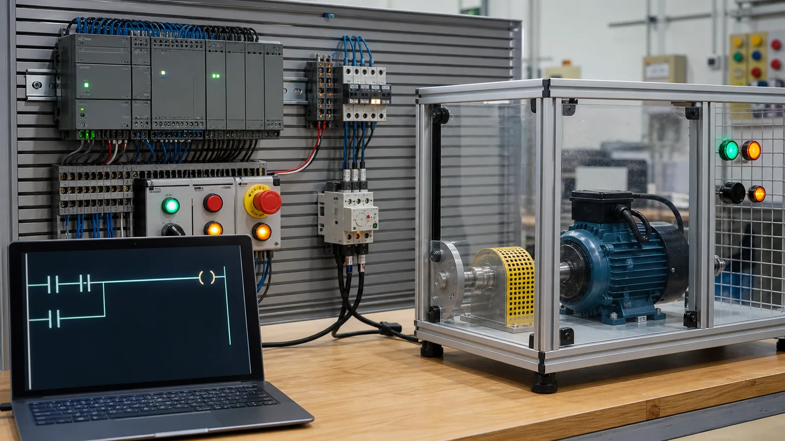
S7-style addressing, blocks and timers
Siemens PLC simulator: S7 logic practice before TIA Portal and PLCSIM
Direct answer
A Siemens PLC simulator for learning lets you practice S7-style logic, %I and %Q addressing, set and reset coils, IEC timers and SCL in a browser without a TIA Portal license. This one is an independent learning tool, not S7-PLCSIM: use it to build and test the control reasoning, then recreate the program in TIA Portal and verify it on PLCSIM or the target CPU.
This guide is written for learners preparing for Siemens-based roles or courses, technicians moving from Allen-Bradley or relay logic to S7 conventions, and anyone who wants to rehearse SCL and LAD patterns before they have TIA Portal access. The intended result is specific: you can read and write Siemens-style addresses and SCL, explain how an IEC timer instance, a set/reset pair and the main program cycle interact, and list what must be rebuilt and re-tested when the logic moves into a real TIA Portal project.
Byte.bit addressing
Siemens digital addresses name a byte and a bit: %I0.0 to %I0.7 are the eight bits of input byte 0, and the next input is %I1.0, not %I0.8. Outputs use the same form in the %Q area, word access uses %IW or %QW, and in TIA Portal the program normally displays the symbolic tag name mapped to each address.
Overlapping memory areas
Marker word %MW10 contains bytes %MB10 and %MB11, and double word %MD10 spans %MW10 and %MW12. Siemens stores the high-order byte at the lower address, so writing %MW10 also changes bits %M10.0 to %M11.7. Reusing overlapping addresses for unrelated values is a classic cause of flags changing with no visible instruction.
OB1 and the call tree
In an S7 CPU the program cycle organization block, OB1 by default, runs repeatedly, and functions (FC) or function blocks (FB) execute only when a block in that tree calls them. Startup initialization belongs in a startup OB such as OB100. Code that compiles but is never called is downloaded to the CPU and simply never runs.
Instance data for timers
An IEC TON in TIA Portal keeps its elapsed time and state in instance data: a single-instance DB, a multi-instance inside the calling FB, or a tag of type IEC_TIMER. Each running timer needs its own instance. Two calls sharing one instance overwrite each other’s state, which makes a delay look random or never complete.
Set/reset priority
With separate S and R coils, the instruction executed later in the cycle determines the stored bit when both conditions are true. Siemens also provides flip-flop boxes: SR is reset-dominant and RS is set-dominant. Choose the dominance deliberately, because a stop or fault reset should normally win over a held start request.
SCL and LAD, one decision
SCL, the Siemens form of Structured Text, suits calculations, comparisons and state logic, while LAD shows contact and coil paths that maintenance staff trace online. Writing one requirement both ways, such as #Run := (#Start OR #Run) AND NOT #Stop, shows that the language changes readability, not the result the cycle produces.
- 01
Fix the S7 context
Record the CPU family you will eventually use, a tag list, which values are inputs, outputs, markers or DB data, and which field devices are normally closed.
Evidence: Every signal has a symbolic name, an address area and a stated healthy state.
Avoid: Copying addresses from an example without checking byte and bit numbering.
- 02
Write in the Siemens dialect
Declare tags with AT %I and %Q addresses, then express the logic as SCL assignments or STL-style A, AN, O and = operations.
Evidence: The program compiles and the live I/O view shows the addresses you declared.
Avoid: Assuming every TIA Portal addressing form is accepted; read the compile message and the dialect notes.
- 03
Add timers with typed presets
Declare one TON instance per delay, call it on every cycle with IN and a T# preset, and read .Q in a separate assignment.
Evidence: Elapsed time rises only while IN is held and returns to zero when IN drops.
Avoid: Writing a bare integer preset or calling one timer instance from two places.
- 04
Test set/reset and interlocks
Press start and stop together, hold a fault input, and release inputs in unusual orders.
Evidence: The stored bit follows the dominance you designed, and stop or fault wins over start.
Avoid: Placing the S coil after the R coil so a held start overrides a stop.
- 05
Run the scenario checks
Execute the authored tests and compare each failed check with your tag list and network order.
Evidence: Per-check results pass on observed behavior, not on matching a model SCL listing.
Avoid: Editing presets or adding latches until a check passes without a stated cause.
- 06
Rebuild in TIA Portal
Create the device configuration, tag table, OB1 calls, FC or FB blocks and timer instances in a real project, then repeat the same test cases in PLCSIM or on the CPU.
Evidence: The same input sequences produce the same outputs in the Siemens environment.
Avoid: Treating the browser program as an importable project or as proof of cycle time.
| Observed symptom | Inspect | Interpretation | Next proving action |
|---|---|---|---|
| Input changes but the logic ignores it | Module start address in device configuration, the tag table address and the byte.bit used in the logic | I/O addresses come from the hardware configuration, so a tag on %I0.0 can point at a byte no module is mapped to. | Compare the module address range with the tag table before editing logic. |
| Block logic never executes | Whether the FC or FB is called from OB1 or another called block, and whether that call is conditional | A block outside the call tree of a running OB compiles and downloads but is never executed. | Add the call or remove the condition around it, then monitor the block online. |
| TON restarts or finishes early | Instance DB or IEC_TIMER tag used by each timer call, and whether IN stays true every cycle | Two calls sharing one instance, or IN dropping for a single cycle, resets or corrupts the elapsed time ET. | Give each timer its own instance and trace IN in a watch table or trace. |
| Motor starts while Stop is pressed | Order of the S and R coils, or which flip-flop box, SR or RS, holds the run bit | When both conditions are true the later instruction or the dominant input wins; a set-dominant arrangement lets a held start override stop. | Make stop and fault resets dominant and retest simultaneous commands. |
| Flags change unexpectedly | Every use of overlapping marker or DB addresses such as %MW10, %MB11 and %MD10 | Word and double-word access overlaps byte and bit ranges, so an unrelated MOVE can overwrite a status bit. | Use symbolic tags in an optimized DB, or give each word a non-overlapping address. |
| Values reset after a restart | Retain settings on DB and marker tags, startup OB logic, and whether OB100 writes the value | Non-retentive data returns to its start value on a warm restart, and startup code can overwrite values that were retained. | Set retentivity deliberately and test the restart on PLCSIM or the CPU. |
Product evidence / 05
What the browser practice can actually demonstrate
The Siemens SCL learning dialect accepts VAR declarations with AT %I and %Q addresses, SCL assignments, TON calls with T# time literals and STL-style A, AN, O, =, S and R operations, then runs them on the same deterministic scan and behavior-based scenario tests as the other dialects.
What does %I0.0 mean in a Siemens PLC?
It is input byte 0, bit 0. The % marks an absolute operand in TIA Portal, I is the process-image input area, and bits run from 0 to 7 before moving to the next byte. %Q0.0 is the matching output bit, %M0.0 a marker bit and %IW2 an input word. Programs usually show symbolic tag names mapped to these addresses.
What is OB1 in a Siemens PLC?
OB1 is the default program cycle organization block. The CPU updates the process images, runs OB1 and every block it calls, and repeats. Other OBs handle startup, cyclic interrupts, hardware interrupts and errors, which is why moving logic from OB1 into another OB changes when, and how often, it runs.
How does a TON timer work in TIA Portal?
TON starts timing when IN becomes true, reports elapsed time on ET and sets Q once ET reaches the preset PT, written as a TIME literal such as T#5s. If IN goes false, ET returns to zero and Q resets. Each call needs its own instance data, created as an instance DB, a multi-instance or an IEC_TIMER tag.
Why does only the last network that writes an output seem to work?
If two networks assign the same output, both execute and the later one overwrites the process-image value before it is written to the module. The earlier network therefore appears to be ignored. Keep one assignment per output and combine the conditions there, or use deliberate set and reset instructions with a defined priority.
What is the difference between SR and RS in Siemens?
Both are bistable flip-flop boxes backed by a memory bit. In SR the reset input is dominant, so the output stays off while both inputs are true; in RS the set input is dominant. Reset-dominant logic is the usual choice for stop and fault paths, although safety functions still belong in rated safety hardware and logic.
Should I learn SCL or LAD first for Siemens?
Learn LAD first if you will troubleshoot machines, because contacts, coils and online status map directly to physical signals. Learn SCL early if you will write calculations, recipes or state machines. Many S7 projects mix both, so reading the same logic fluently in either form is more useful than preferring one.
What is a DB and what does optimized block access change?
A data block holds data outside the code that uses it: global DBs for shared values and instance DBs for FB and timer state. With optimized block access, TIA Portal arranges the data itself, so tags are reached symbolically instead of through absolute offsets such as DB1.DBX0.0, and retentivity is set per tag.
How do I move a program from this simulator into TIA Portal?
Treat the browser program as a tested design, not a file. In TIA Portal, add the CPU and modules, build the tag table from your I/O list, place the logic in OB1 or a called FC or FB, create timer instances and compile. Then repeat the same input sequences in PLCSIM or on the CPU before any commissioning.