Direct answer: A direct-on-line motor starter has a three-phase power circuit and a low-power control circuit. The power circuit runs through short-circuit protection, a three-pole contactor and an overload relay to the motor. The control circuit energises the contactor coil through Stop, overload and safety contacts; a Start command and auxiliary seal-in contact keep it running.
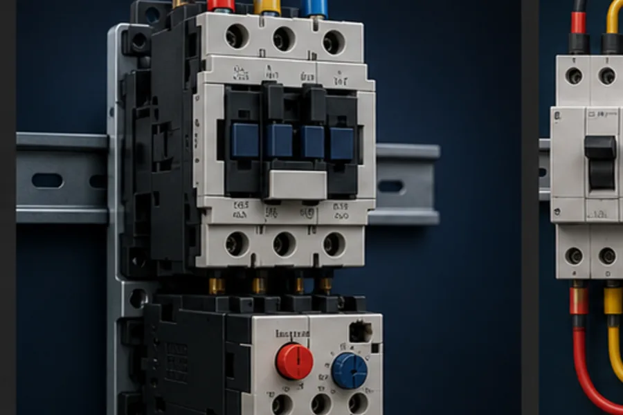
Reading those two circuits separately makes a motor starter diagram far easier. The power circuit answers “can energy reach the motor?” The control circuit answers “should the contactor be pulled in right now?”
The four devices in a DOL starter
- Short-circuit protective device: fuse, motor-protection breaker or coordinated circuit breaker.
- Contactor: an electromagnetic switch that opens/closes all three motor phases.
- Overload relay: detects sustained overcurrent/phase loss and opens the contactor coil path.
- Control station or PLC: supplies the run request after permissives are true.
A motor starter is not just a contactor. The overload is what turns the switching device into a basic protected starter.
Power circuit: line to motor
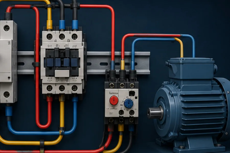
The common IEC power path is:
L1 ─ protective device ─ contactor 1/L1 → 2/T1 ─ overload L1/T1 ─ motor U
L2 ─ protective device ─ contactor 3/L2 → 4/T2 ─ overload L2/T2 ─ motor V
L3 ─ protective device ─ contactor 5/L3 → 6/T3 ─ overload L3/T3 ─ motor W
PE ───────────────────────────────────────────────────── motor frame
The contactor handles switching. The overload heaters/current sensors see the same motor current. The upstream protective device must be coordinated for fault current and the installation's applicable code.
The protective-earth conductor does not pass through the contactor or overload. It bonds exposed conductive parts according to the approved design.
Control circuit: start, hold and stop
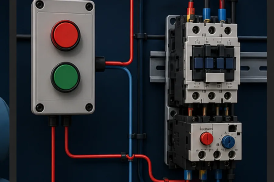
The classic three-wire circuit is:
+24 V ─ E-STOP/SAFETY ─ STOP NC ─ OL 95–96 NC ─┬─ START NO ───┬─ K1 A1
                                                └─ K1 13–14 NO ┘
0 V  ─────────────────────────────────────────────────────────── K1 A2
State sequence
- Stop and overload contacts are closed in the healthy state.
- The operator presses Start.
- K1 coil energises and pulls in the main contacts.
- K1 auxiliary contact 13–14 closes in parallel with Start.
- Releasing Start no longer breaks the circuit; 13–14 holds the coil.
- Stop, safety removal or overload trip opens the series path.
- K1 drops out, opening the power poles and the holding contact.
This is undervoltage protection too: after control power fails, the contactor drops out and the seal-in opens. Restoring power does not restart the motor until Start is intentionally pressed again.
How the overload stops the starter

The motor current does not flow through 95–96. That small NC auxiliary contact sits in the control circuit. A thermal or electronic trip changes the auxiliary state, breaking A1's supply and allowing the contactor spring to open the main poles.
The companion 97–98 NO contact can close into a PLC input or alarm lamp. This lets the HMI say Motor overload tripped instead of the unhelpful Motor failed.
For the full mechanism and trip-class explanation, see thermal overload relay: how it works.
PLC-controlled starter
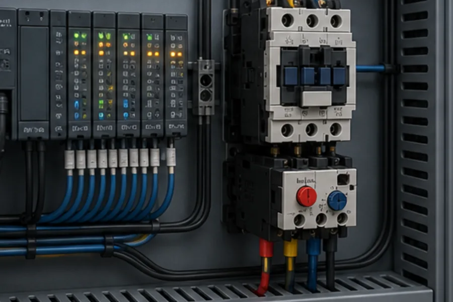
In a PLC system, ladder logic usually replaces the hardwired Start seal-in, while hardwired protection and safety remain as required by the risk assessment and standard.
Typical signal set:
| PLC tag | Type | Physical meaning |
|---|---|---|
START_PB | input | momentary operator request |
STOP_OK | input | stop circuit is healthy |
OVERLOAD_TRIPPED | input | overload 97–98 changed state |
K1_AUX | input | contactor physically pulled in |
K1_COIL | output | request to energise contactor coil |
Conceptual ladder logic:
Rung 1  RUN_CMD = STOP_OK AND NOT OVERLOAD_TRIPPED
                  AND (START_PB OR RUN_CMD)

Rung 2  K1_COIL = RUN_CMD AND ALL_PERMISSIVES

Rung 3  IF K1_COIL AND NOT K1_AUX after proof time → FAIL_TO_START
        IF NOT K1_COIL AND K1_AUX after dropout time → WELDED_CONTACTOR
The output command is not proof that power reached the motor. An auxiliary contact provides physical feedback, while a current switch or drive feedback can provide stronger proof where the process requires it.
Direct output or interposing relay?
Check the PLC output module and coil data. Contactor coils can have significant pickup current and generate an inductive transient at dropout. An interposing relay or purpose-rated output can protect the PLC module and make replacement easier. Match AC/DC type and suppression.
Safety circuits are not ordinary PLC permissives
An emergency stop is a risk-reduction function, not merely another HMI command. The architecture may require a safety relay/safety PLC, dual channels, monitored reset and contactor feedback. A standard PLC input alone is not a substitute for the required safety performance level.
The starter logic should still expose safety state to the ordinary PLC for diagnostics, but the safety function must not depend solely on non-safety software when the risk assessment requires certified hardware.
Commissioning the sequence
Safety: these circuits can contain lethal voltage and unexpected motion. Only qualified people following the site's isolation, lockout/tagout and commissioning procedures should work on physical equipment.
A disciplined functional test is more useful than checking Start alone:
- Confirm ratings, conductor identification, terminations and protective coordination.
- With motive power safely isolated as the procedure requires, prove the control sequence and feedback.
- Press Start: K1 command and K1 auxiliary must follow within the expected time.
- Press Stop: command and feedback must drop out.
- Test the approved overload function: the starter must drop and expose the correct diagnostic.
- Test loss/restoration of control power: the motor must not restart unexpectedly.
- Test safety removal and monitored reset according to the safety validation plan.
- Restore motive power under controlled conditions and check phase current, rotation and load.
Common diagram mistakes
- Wiring Start as a maintained command without a deliberate restart analysis.
- Omitting overload 95–96 from the coil path.
- Treating 97–98 as a motor-power contact.
- Using the wrong coil voltage.
- Driving a coil beyond the PLC output rating.
- Using command state as the only proof of contactor operation.
- Allowing automatic restart when power or a fault clears.
- Drawing an E-stop as ordinary software only.
Build it in the browser
Start with the Three-wire Motor Starter lesson, which separates the power and control paths and lets Pro learners interact with the seal-in state. Then use the Motor Start/Stop scenario to build, run and fault-test the ladder sequence.
If the motor already refuses to start, use the motor starter troubleshooting sequence to isolate the coil, overload and field-wiring zones.
Frequently asked questions
What is the difference between a contactor and motor starter?
A contactor switches the motor. A motor starter combines the contactor with overload protection and the necessary control/protection arrangement.
Why is the Stop button normally closed?
Opening the Stop circuit must remove coil power. A normally-closed circuit also turns a broken wire or lost control supply into a stop rather than an ignored command.
What makes a three-wire starter latch?
The contactor's NO auxiliary contact closes in parallel with the momentary Start button. After Start is released, the auxiliary contact keeps the coil energised until a series Stop/overload/safety contact opens.
Does a PLC eliminate the overload relay?
No. The PLC can monitor motor current and add diagnostics, but the motor still needs the protection required by the coordinated electrical design. A VFD or electronic motor-protection relay may provide that function in another architecture.
Why will a starter not restart after an overload reset?
Possible causes include a still-open 95–96 contact, an unacknowledged PLC fault latch, missing safety reset, open Stop circuit, wrong reset mode or a contactor coil/control-supply fault. Diagnose the state rather than bypassing it.
