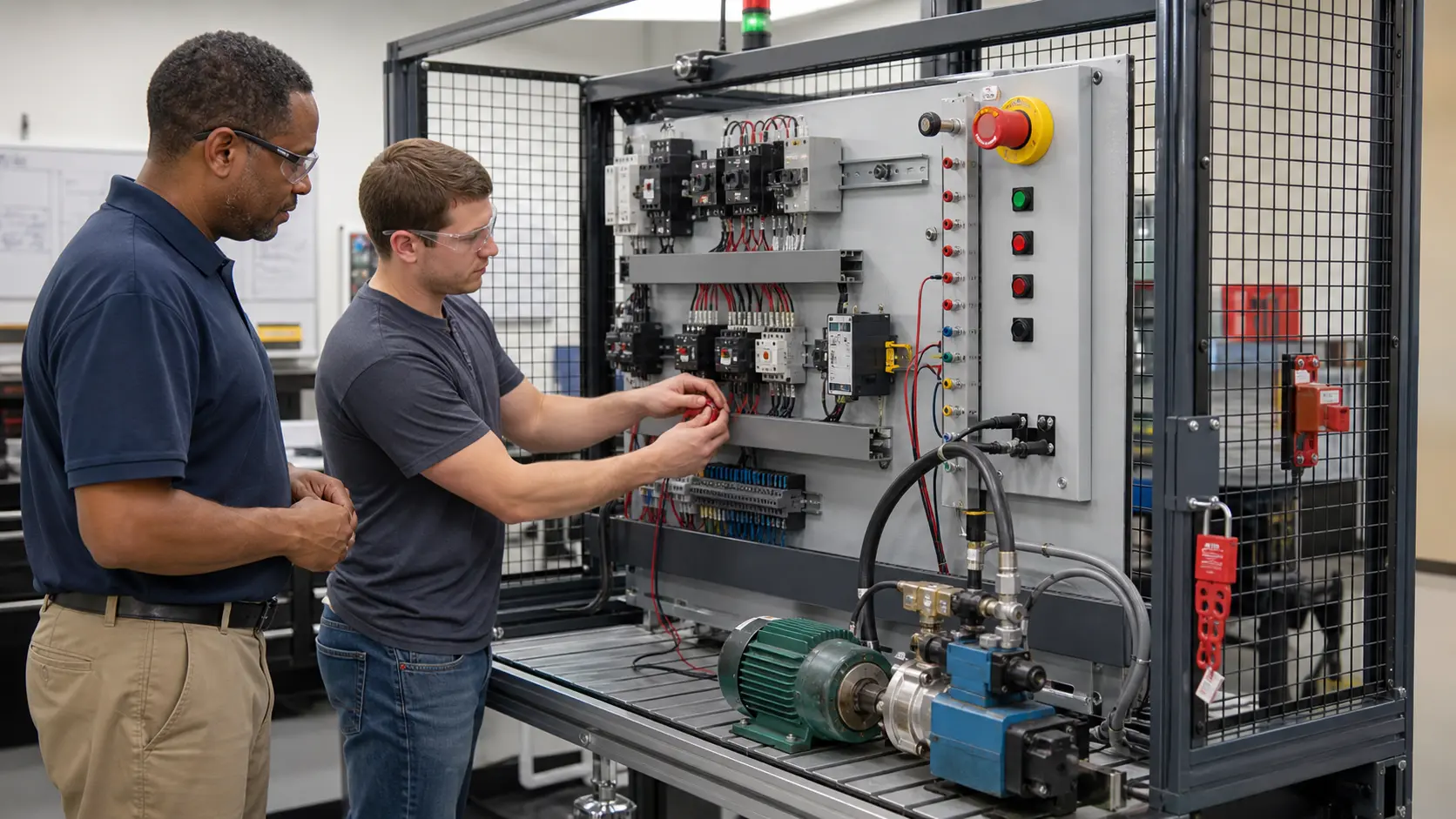
Direct answer: A thermal overload relay protects a motor from overheating during sustained overcurrent or phase loss. Motor current heats three bimetal elements. If the heat accumulates beyond the relay's calibrated limit, a trip mechanism opens the normally-closed 95–96 control contact, the contactor coil drops out, and the motor stops. It does not replace the short-circuit protection supplied by a fuse or circuit breaker.
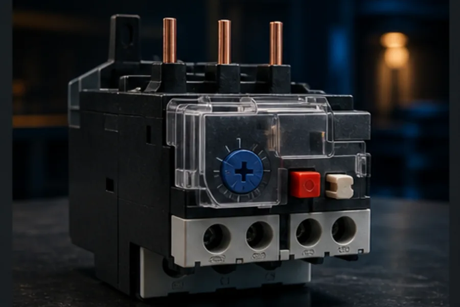
That one paragraph explains the complete cause-and-effect chain, but a technician needs to understand each link: why the relay reacts slowly to a modest overload, why it reacts faster to a severe one, why the motor power does not pass through terminals 95 and 96, and why pressing Reset without finding the cause is poor fault-finding.
What a thermal overload relay protects
A motor overload is not the same fault as a short circuit.
| Condition | Typical current | Correct protection |
|---|---|---|
| Normal running | Near motor nameplate full-load current | No trip |
| Mechanical overload, jam or failing bearing | Moderately above full-load current for seconds or minutes | Thermal/electronic overload relay |
| Phase loss | High and unbalanced current in the remaining phases | Phase-sensitive overload relay |
| Short circuit | Extremely high current in milliseconds | Fuse or circuit breaker |
The overload relay is deliberately inverse-time: more current creates heat faster, so a larger overload trips sooner. This allows a motor's brief starting current without nuisance-tripping while still stopping a stalled or overworked motor before its windings exceed a safe temperature.
ABB describes thermal overload relays as motor-protection devices for overload and phase failure that combine with a contactor to form a starter. Schneider's trip-class guidance explains that the class must match the motor's starting characteristic, not a guess made at commissioning. See the primary references at the end of this guide.
What physically moves inside the relay
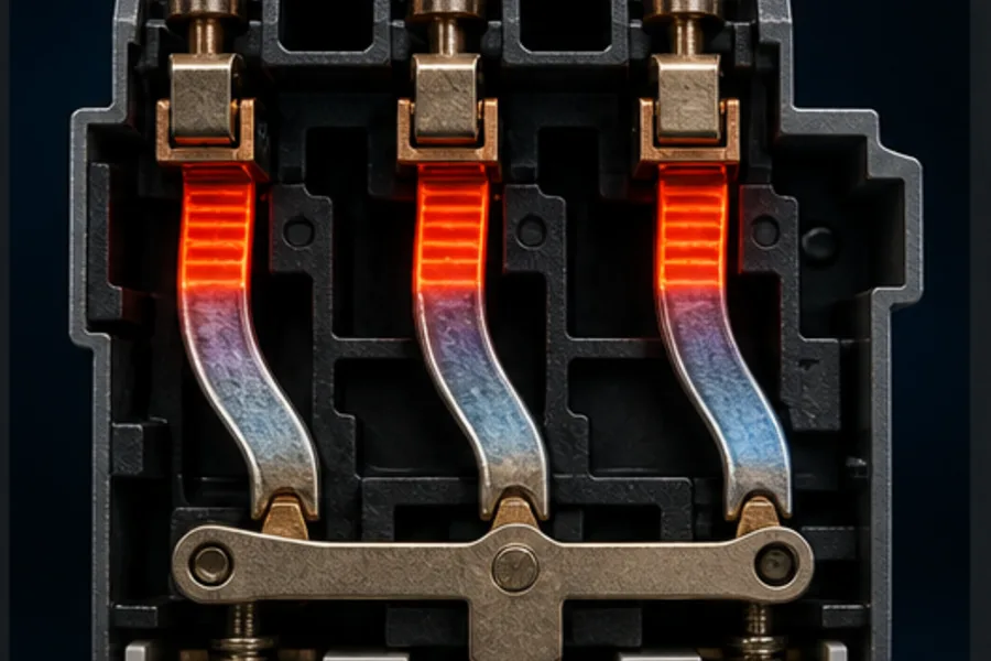
In a common three-pole thermal overload relay, each motor phase passes through a small heater associated with a bimetal strip. A bimetal is made from two bonded metals that expand at different rates. Heating makes the strip curve.
The sequence is:
- Motor current flows through all three power paths.
- Each path heats in proportion to current and time.
- The bimetal strips bend as their temperature rises.
- Their combined movement loads a mechanical trip bar.
- At the calibrated point, the mechanism snaps to the tripped state.
- The 95–96 contact opens and 97–98 closes.
- The open control circuit de-energises the contactor coil.
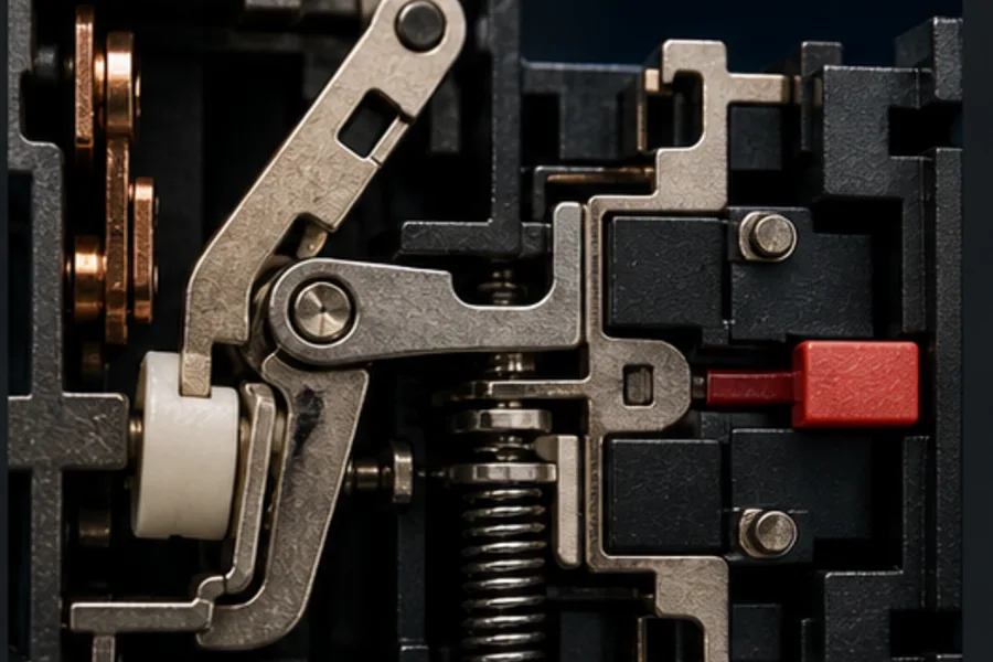
The trip mechanism is normally snap-action rather than a contact that slowly drifts apart. That provides a decisive change of state and prevents the contactor coil from hovering at an uncertain voltage.
Electronic overload relays estimate the same thermal condition from current sensors and a digital model. They can add phase-loss, current-imbalance and communication diagnostics, but the system job remains the same: interrupt the contactor control circuit before sustained current damages the motor.
How the contactor and overload work together
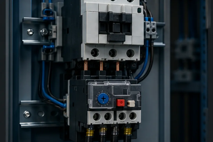
A direct-on-line motor starter is the combination of:
- a short-circuit protective device upstream;
- a contactor that switches motor power on command; and
- an overload relay that decides when sustained motor current is unsafe.
The contactor handles frequent switching. The overload does not normally switch the motor's main current off by itself. Instead, its small NC auxiliary contact opens the coil circuit, causing the contactor's main poles to open together.
This separation is important. A PLC output may command the contactor coil, but a correctly designed overload contact can still remove that command path if the motor overheats. The PLC should also receive an overload status input so it can explain why the motor stopped and block an inappropriate restart.
What 95–96 and 97–98 mean
IEC overload relays commonly use these terminal numbers:
| Terminals | Normal state | State after trip | Typical job |
|---|---|---|---|
| 95–96 | Closed | Open | Wired in series with the contactor coil to stop the motor |
| 97–98 | Open | Closed | Signals OVERLOAD_TRIPPED to a PLC input or alarm lamp |
The three large incoming/outgoing paths carry the motor current. The small 95–96 and 97–98 terminals are auxiliary contacts only. Do not confuse those two circuits.
A typical control path is:
+24 V → safety permissives → STOP (NC) → overload 95–96 (NC)
      → PLC/START command → contactor coil A1 → A2 → 0 V
The fault feedback is separate:
+24 V → overload 97–98 (NO) → PLC input OVERLOAD_TRIPPED
What the current dial changes
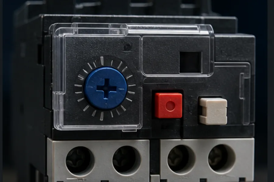
The current dial calibrates the relay to the motor. It is commonly set from the motor nameplate current and the manufacturer's coordination instructions. It is not a convenient way to “make nuisance trips go away.” Turning the dial above the value required by the motor and installation can remove the protection the relay is meant to provide.
The correct setting depends on the specific relay, motor service factor, ambient compensation, wiring method and applicable standard. Use the relay and motor documentation; do not infer a universal percentage from an online example.
What trip class means
Trip class describes the relay's time characteristic at a stated multiple of its current setting. Schneider's North American guidance describes Class 10, 20 and 30 as tripping within approximately 10, 20 or 30 seconds respectively at six times the setting. IEC coordination uses defined curves and cold/hot starting conditions, so always read the exact relay data.
- Class 10/10A: typical normal-starting motors.
- Class 20: longer or heavier starts where the motor and application require it.
- Class 30: very long acceleration duties, only when the coordinated design calls for it.
A slower trip class is not “better.” It permits more thermal energy during a start and must match the motor and load.
What happens during a real jam
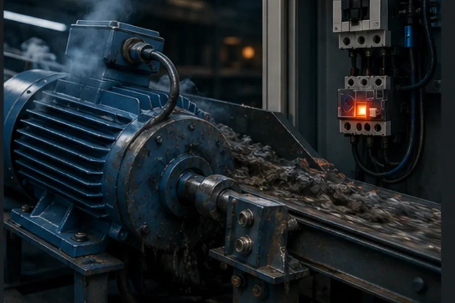
Suppose a conveyor bearing seizes. The PLC output remains true because the sequence still wants the conveyor to run. The motor slows or stalls and current rises. The overload's thermal state accumulates until it trips.
A robust PLC program should then:
- see the 97–98 overload input;
- remove the motor run command;
- latch a clear
MOTOR_OVERLOADdiagnostic; - prevent automatic restart;
- require the physical cause to clear and an intentional reset/acknowledgement; and
- detect a contactor that remained physically closed through auxiliary feedback.
The overload is field protection. The PLC logic supplies sequencing, explanation and restart discipline. Neither replaces the other.
Safe troubleshooting sequence
Safety: motor starters can contain lethal voltage and stored mechanical energy. Apply the site's isolation, lockout/tagout and verification procedure. The browser lab below is for learning; it is not permission to work live.
When an overload has tripped:
- Record what the machine was doing and whether the motor was starting, running or mechanically blocked.
- Inspect the trip indicator before disturbing the controls.
- Verify the overload setting against the motor and approved design.
- Check for a jam, tight bearing, blocked pump, phase loss, voltage imbalance or repeated starts.
- Allow a thermal device to cool for the manufacturer's required time.
- Reset only after the underlying condition is safe.
- Run under observation and compare phase currents rather than repeatedly pressing Reset.
Repeated trips are evidence, not an inconvenience to bypass.
Practise the complete cause-and-effect chain
The Thermal Overload lesson lets you energise a motor, raise its simulated load, watch the bimetal mechanism accumulate heat, see 95–96 open, and observe the contactor and PLC state change. The recognition content is public; the interactive cutaway and contextual AI tutor are Pro features.
Then apply it in the Motor Start/Stop scenario, where the overload is one permissive in a complete seal-in and fault-latch program.
Frequently asked questions
What is a thermal overload relay in plain English?
It is a reusable motor-protection device that estimates motor heating from current. When too much current flows for too long, it opens a small control contact that makes the contactor switch the motor off.
Does an overload relay protect against a short circuit?
No. Its response is intentionally slower so the motor can start. A fuse or circuit breaker provides short-circuit protection; the overload relay provides sustained-overcurrent protection.
Why is overload contact 95–96 normally closed?
The contact must conduct during healthy operation. A trip opens it and breaks the contactor coil circuit. That fail-to-open action is why 95–96 is placed in series with the coil command.
What is 97–98 used for?
It is normally open and closes when the overload trips. It is commonly wired to a PLC digital input or alarm indicator so the control system can state the real stop reason.
Can I reset an overload relay immediately?
Only after the device has cooled enough to reset and the cause has been made safe. A reset without diagnosis can restart a jammed, single-phasing or otherwise damaged motor.