Pump control logic in a PLC almost always comes down to one idea: start the pump on a low-level signal, hold it on with a seal-in, and stop it on a high-level signal. Everything more advanced — duty/standby redundancy, lead-lag staging, run-hour balancing and automatic fault changeover — is built on top of that single self-holding rung. Once you can read one pump rung you can read a whole pump station.
This guide builds it up from a single pump to a full lead-lag pair, with ladder rungs, a state diagram, a timing diagram and an architecture sketch for each step.
The hardware: what the PLC actually sees
A typical wet-well or tank fill uses two level switches and two pumps. The PLC reads a high-level and a low-level input and drives a contactor for each pump. That is the whole I/O picture for most pump-control jobs.
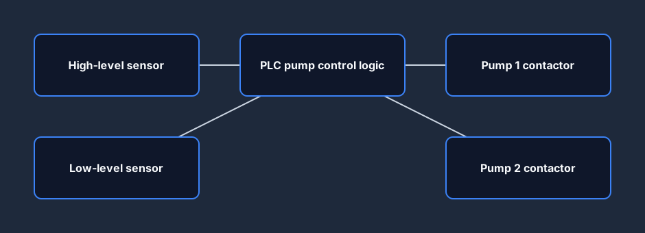
The level switches can be floats, conductive probes, or thresholds derived from a 4-20 mA level transmitter — the logic is identical. What matters is that you have one signal that says "we need to pump" and one that says "we can stop."
The core rung: start, seal-in, stop
Here is the rung that does 90% of the work. The low-level contact starts the pump. The pump's own run output is wired in parallel as a seal-in so it stays on after the level rises above the low switch. A normally-closed high-level contact breaks the rung and stops the pump once the tank is full (or, for a drain application, empty).
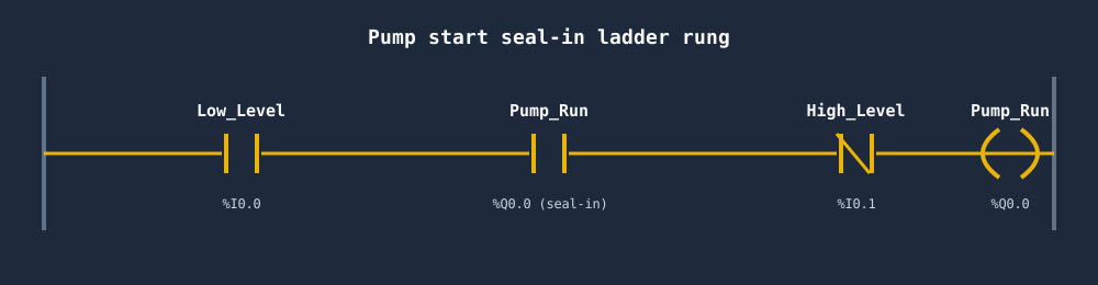
If the seal-in is new to you, it is exactly the same self-holding pattern used for motor start/stop circuits — read seal-in rungs explained for the why behind the parallel contact. Without the seal-in the pump would chatter on and off every time the level brushed the low switch.
In practice you add a short TON on-delay on the start so a sloshing level switch cannot rapid-cycle the contactor. A few seconds of delay rides through the chatter without affecting the process.
Reading the level vs the pump
The timing diagram makes the behavior obvious. As the tank drains, the level falls until the low switch trips and the pump runs. The pump fills the tank, the level climbs, and at the high switch the pump stops. Then the cycle repeats.
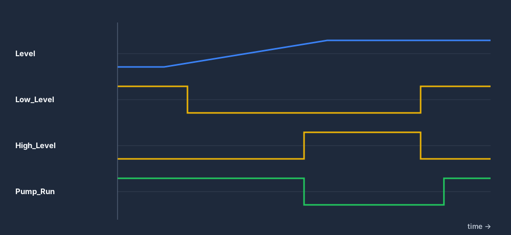
Notice the deadband between the low and high switches. That gap is what stops the pump short-cycling — a pump that starts and stops dozens of times an hour will burn out its motor and contactor. The wider the gap, the fewer starts, but the larger the level swing you can tolerate.
Two pumps: duty/standby
One pump is a single point of failure. The standard fix is a second, identical pump configured as duty/standby: one pump (the duty) does the work, the other (the standby) sits idle, ready to take over if the duty pump faults.
Two refinements turn a pair of pumps into a proper duty/standby system:
- Alternation — swap which pump is "duty" each cycle so both accumulate roughly equal run hours. A pump that never runs seizes; a pump that always runs wears out first.
- Fault changeover — if the duty pump trips on overload or reports no flow, the logic promotes the standby pump automatically and raises an alarm.
The alternation itself is just a state machine that flips the lead pump every completed fill cycle.
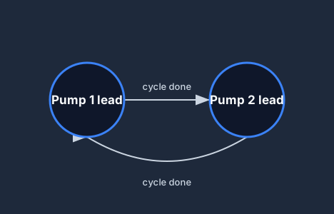
A common way to implement alternation is a single boolean that toggles on each falling edge of the run output: if it is set, Pump 1 is duty this cycle; if clear, Pump 2 is. You can also alternate on real run hours — pick whichever pump has the fewest accumulated hours — which keeps wear even when one pump runs longer than the other.
More demand: lead-lag
Lead-lag (sometimes called lead-follow) is duty/standby that can run both pumps at once when one cannot keep up. The lead pump starts first on low demand. If the level keeps rising — or a high-demand threshold is crossed — the lag pump starts too and they pump together. As demand falls, the lag pump drops out first, then the lead.
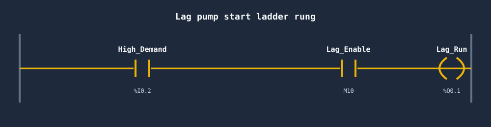
The lag rung sits alongside the core start rung: it only energises when a high-demand condition is true and the alternation logic has enabled this pump as the lag for the cycle. Combine that with fault changeover and you have the full decision flow.
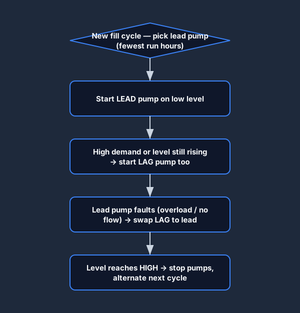
Each cycle the logic selects the lead pump (typically the one with the fewest run hours), starts it on low level, brings in the lag pump on high demand, swaps to the standby on a fault, and stops everything at the high-level mark before alternating for next time.
Pump-control best practice
A few habits separate a pump program that survives years in the field from one that nuisance-trips every week.
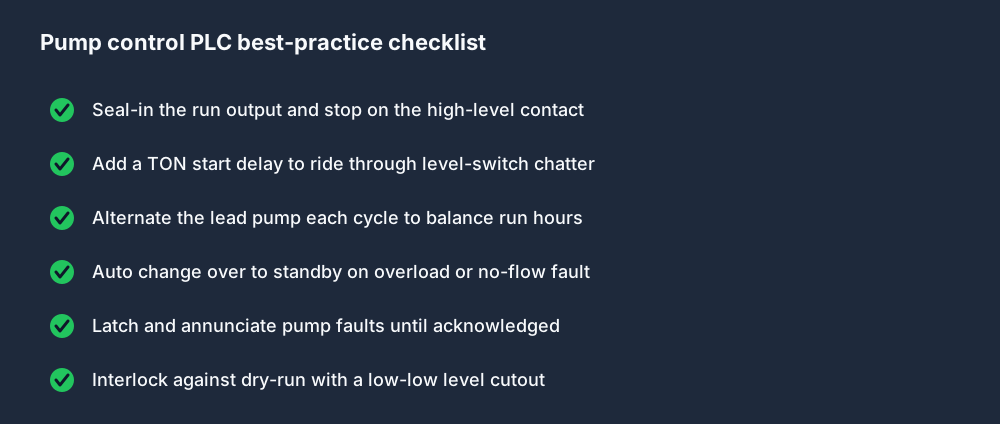
The two that catch beginners most often are dry-run protection — a low-low cutout so the pump never runs against an empty well — and latched fault annunciation, so a momentary overload does not silently clear itself before anyone notices the pump was struggling.
Which strategy do you need?
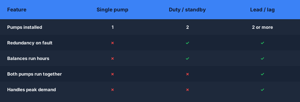
In short: a single pump is fine for non-critical, low-duty service. Duty/standby adds redundancy and balances wear for anything you cannot afford to lose. Lead-lag adds the ability to stage extra capacity for peak demand on top of that redundancy.
Build it in your browser
The fastest way to make pump logic stick is to wire the rung, toggle the level inputs, and watch the seal-in hold and the high-level contact drop it out. You can do exactly that in the free browser PLC simulator — build the start/stop rung, add alternation, then break a pump and watch the changeover. Several ready-made PLC practice scenarios cover level and pump control end to end.
FAQ
What is duty/standby pump control in a PLC? Duty/standby runs one pump (the duty) while a second identical pump (the standby) waits idle. The PLC alternates which pump is duty each cycle to balance run hours and automatically switches to the standby if the duty pump faults.
What is the difference between duty/standby and lead-lag? In duty/standby only one pump runs at a time and the other is a backup. In lead-lag the lead pump runs first and the lag pump joins it when one pump cannot meet demand, so both can run together.
How does pump alternation work in ladder logic? A boolean (or a run-hours comparison) decides which pump is lead for the cycle. It toggles each time a fill cycle completes, so the lead role swaps between the pumps and their run hours stay roughly equal.
Why does my PLC pump short-cycle on and off? The deadband between your low-level start and high-level stop is too small, or you are missing a seal-in. Widen the level gap and add a self-holding contact plus a short TON start delay to ride through level-switch chatter.
What stops a PLC pump from running dry? A low-low level cutout (dry-run protection) interlocks the run output so the pump can never start or keep running when the well or tank is empty.