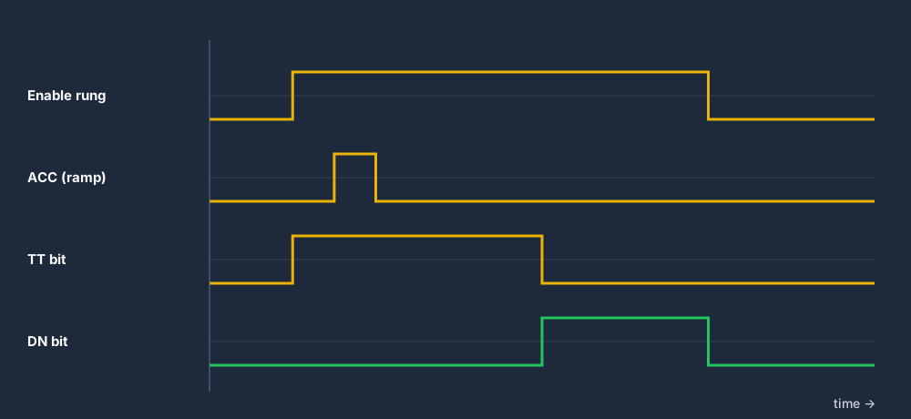
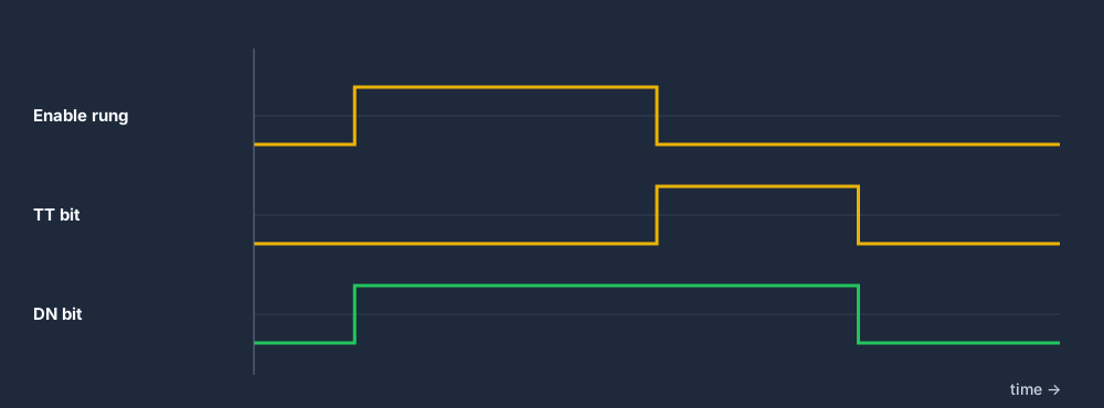
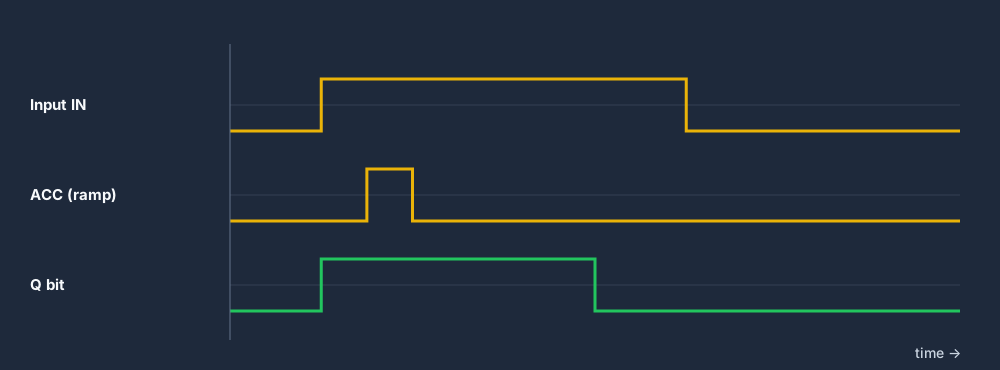
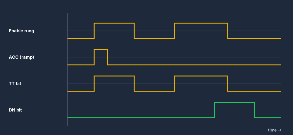
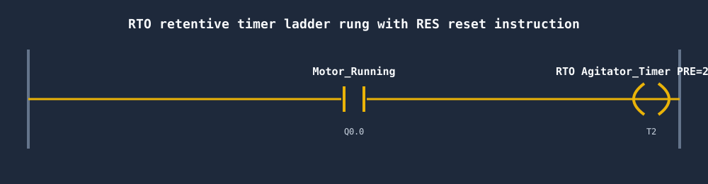
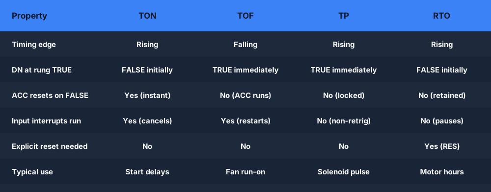
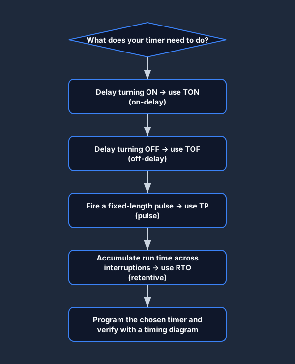
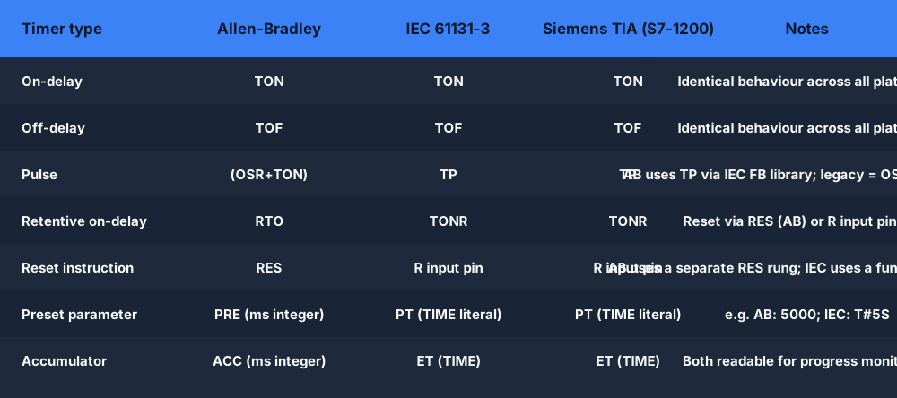
If you remember one line, make it this: TON delays ON, TOF delays OFF, TP makes a fixed pulse. Allen-Bradley adds a fourth, the RTO retentive timer, for totaling time across interruptions.
Unlike a mechanical or electronic timer relay, a PLC timer exists entirely in the controller's memory. There are no physical contacts to wear out, no coil to burn, and the preset value is a number you can change from an HMI or SCADA without rewiring anything.
Every PLC timer, regardless of brand or dialect, has at least three parameters: a preset time (PT / PRE), an accumulated time (ET / ACC), and one or more status bits. Understanding these three elements is the foundation for everything else.
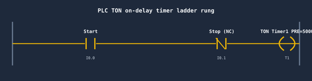
Preset time (PT / PRE). The target duration. When ACC reaches PRE, the timer signals completion. The units depend on the platform. In Allen-Bradley Logix (Studio 5000), PRE is a DINT in milliseconds, so 5000 means 5 seconds. In Siemens TIA Portal and other IEC 61131-3 platforms, you use a TIME literal such as T#5S. In RSLogix 500 / SLC-500, PRE is an integer count of timebase ticks.
Accumulated time (ET / ACC). The running total of time the timer has been timing. Each time the timer instruction executes while enabled, the controller adds the time elapsed since it last executed. Reading ACC in your logic lets you create sub-preset triggers, for example switching on a warning light at 80% of the preset before the final done signal.
Status bits. The bits you actually use in your logic to act on the timer's state. The standard set is:
- .EN / EN — Enable bit. TRUE whenever the rung condition is TRUE and the timer is running (or done).
- .TT / TT — Timer Timing bit. TRUE while the timer is actively counting, FALSE once DN is set or once the rung goes FALSE.
- .DN / Q — Done bit (Allen-Bradley .DN; IEC Q). The bit your output logic usually reads. Its behavior differs between timer types, and that is the key difference between TON, TOF, TP, and RTO.
- .PRE / PT — Readable preset value. You can address this to compare or modify the preset dynamically.
- .ACC / ET — Readable accumulator. Use it to display progress or create cascaded timing logic.
The single most common beginner bug is reading the enable (IN / .EN) in downstream logic when you meant the done bit (Q / .DN). The enable turns on the instant the rung is TRUE, so the "delayed" output fires with no delay at all. Always drive the timed action from Q or .DN.
Timebase matters for inter-operability. Legacy platforms such as Mitsubishi FX and Omron CPM use 100 ms timers by default, while Logix works in milliseconds. Always check your hardware manual: a PRE of 50 on a 100 ms timebase is 5 seconds, but only 50 ms on a 1 ms timebase. The IEC 61131-3 standard avoids this ambiguity with TIME literals (T#5S, T#500MS) rather than raw integers.
In IEC 61131-3 (Siemens TIA Portal, CODESYS, OpenPLC), TON, TOF and TP are function blocks with the same two inputs and two outputs. Only when Q turns on and off changes between them. Here is how each pin maps to an Allen-Bradley TIMER tag:
A timer is not a shared clock. Each one is an instance with its own stored state (its elapsed time and done bit), and that state persists from one scan to the next. Two independent delays need two instances, such as StartDelay and FanRunOn. They can share the TON type, but each keeps its own accumulator.
How the instance is stored depends on the platform. In Allen-Bradley Logix it is a tag of type TIMER with .PRE, .ACC, .EN, .TT and .DN members. In an IEC program it is a variable declared as TON, TOF or TP. In Siemens TIA Portal it lives in an instance data block, or as a multi-instance inside the calling function block.
IEC 61131-3 presets use the TIME data type, written as T# followed by a value and a unit: d (days), h (hours), m (minutes), s (seconds) or ms (milliseconds). Examples: T#500ms, T#5s, T#1m30s, T#2h.
For a preset an operator can change at runtime, wire PT to a TIME variable instead of a literal: