What you'll learn
Wire a 4–20 mA analog output to a smart valve positioner, return its position feedback to an analog input, and connect a HART communicator in parallel across the command loop for commissioning and diagnostics.
Lab time: ~22 minutes.
Lesson briefing
Control Valve with HART Commissioning
Wire a 4–20 mA analog output to a smart valve positioner, return its position feedback to an analog input, and connect a HART communicator in parallel across the command loop for commissioning and diagnostics.
The device in the real world
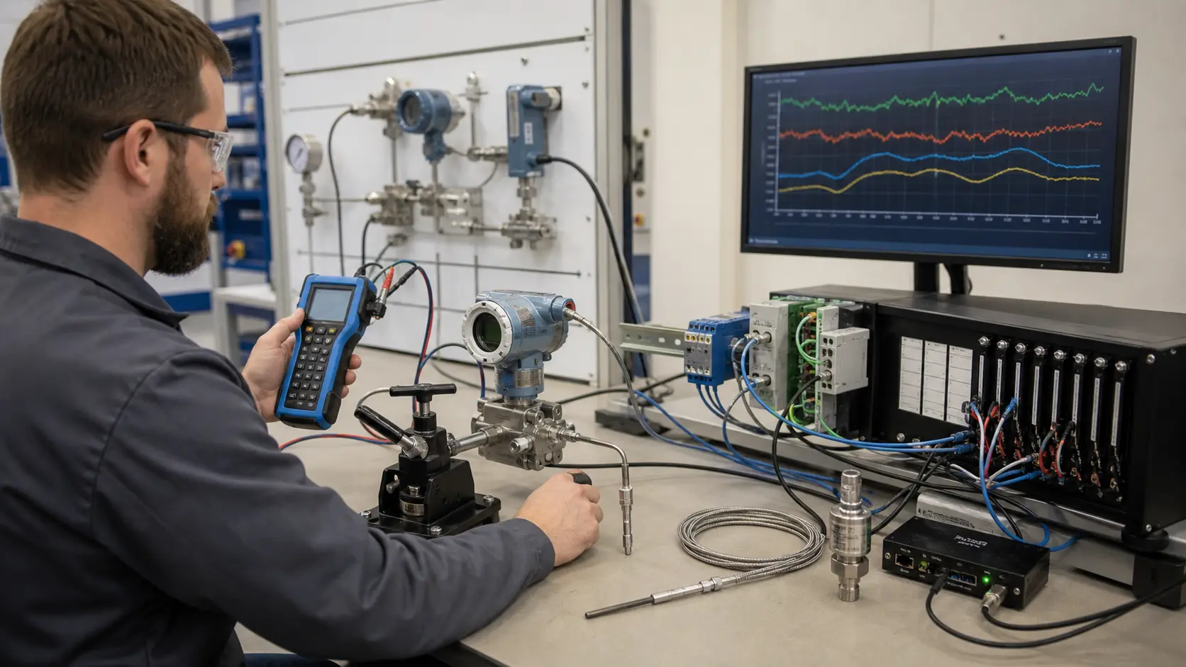
Modern control valves have a smart positioner that moves the valve to match a 4 to 20 mA command, and reports its real position back on a second loop. A HART communicator clips across the command loop and talks to the positioner using a small digital tone riding on the same wires. Technicians use it to read diagnostics and calibrate without disturbing the control signal.
Why it is wired this way
HART superimposes a small digital FSK signal on the 4–20 mA loop. The communicator is connected in parallel, never inserted in series, and the loop needs sufficient impedance for reliable communication.
Worked example
Say the PLC sends 12 mA, which is 50 percent. The positioner moves to half open, and the feedback loop returns about 12 mA to the analog input card. If the feedback reads 14 mA, the PLC sees 62.5 percent, a fixed 12.5 percent error. Because the HART communicator is connected across the loop, not in series with it, you can read both the digital position and the analog current to find out whether the offset is in the valve or the wiring. Wire the lab by starting with the command pair, then the feedback pair, then the communicator.
Common mistakes
- Inserting the communicator in series, which breaks the loop.
- Reversing the polarity of the 4 to 20 mA pair.
- Connecting the feedback pair to the command card.
- Leaving the loop with too little resistance for HART to communicate.
What you can now do
You can wire a command loop and a feedback loop to a smart valve, and connect a HART communicator across the loop for diagnostics.
Commissioning standard
Drive the valve to 0, 50 and 100 percent and compare the command current, the local position and the PLC reading at each point.
Hints
Power both I/O cards and bond their SHIELD terminals to PE.
Sign up to unlock the full hint sequence.
Sign up to unlock the full hint sequence.
This lesson uses 7 placed components on the lab canvas. Components are vendor-neutral (no proprietary trademarks); the wiring rules apply to any equivalent industrial part.
Sign up to preview
Create a free account to preview this Pro lab; upgrade to open the interactive circuit.
Sign up to preview →