PLC Programming: Learn to Program PLCs in Your Browser
PLC programming is writing the control logic that a programmable logic controller runs to operate machines and processes, most often in ladder logic or Structured Text. Every scan, the program reads inputs such as buttons and sensors, makes decisions, and switches outputs such as motors, valves and lights.
Practice with 170 source-catalogued practice records, from traffic lights to PID temperature control, robot handshakes, and CIP sequences, across 9 learning dialects. No install or license key, and no hardware is needed to start.
Watch the real browser product respond to the task on this page, then try the same practical workflow yourself. No slides, concept mockups, install, or credit card.
PLC Programming for Beginners — A Practical Learning Path
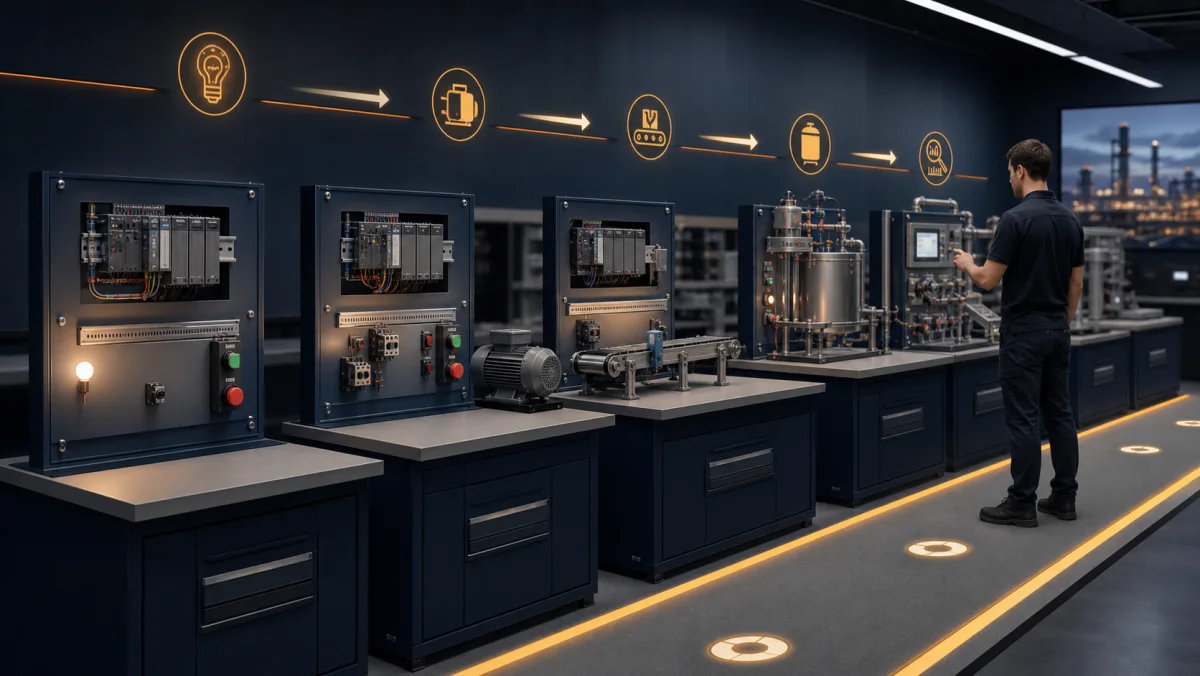
See the whole learning progression
From a field signal to a commissioned control system
PLC programming makes sense when the code stays connected to the machine. These six views show the progression from I/O and scan behavior to language choice, increasing system complexity and supervised hardware practice.
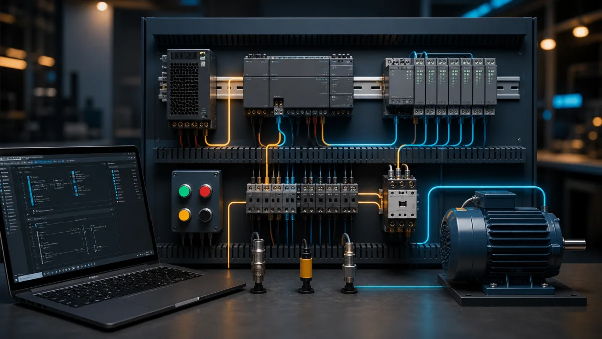
01Start with the complete signal path: a field device changes an input, the CPU evaluates logic, and an output module drives an actuator.
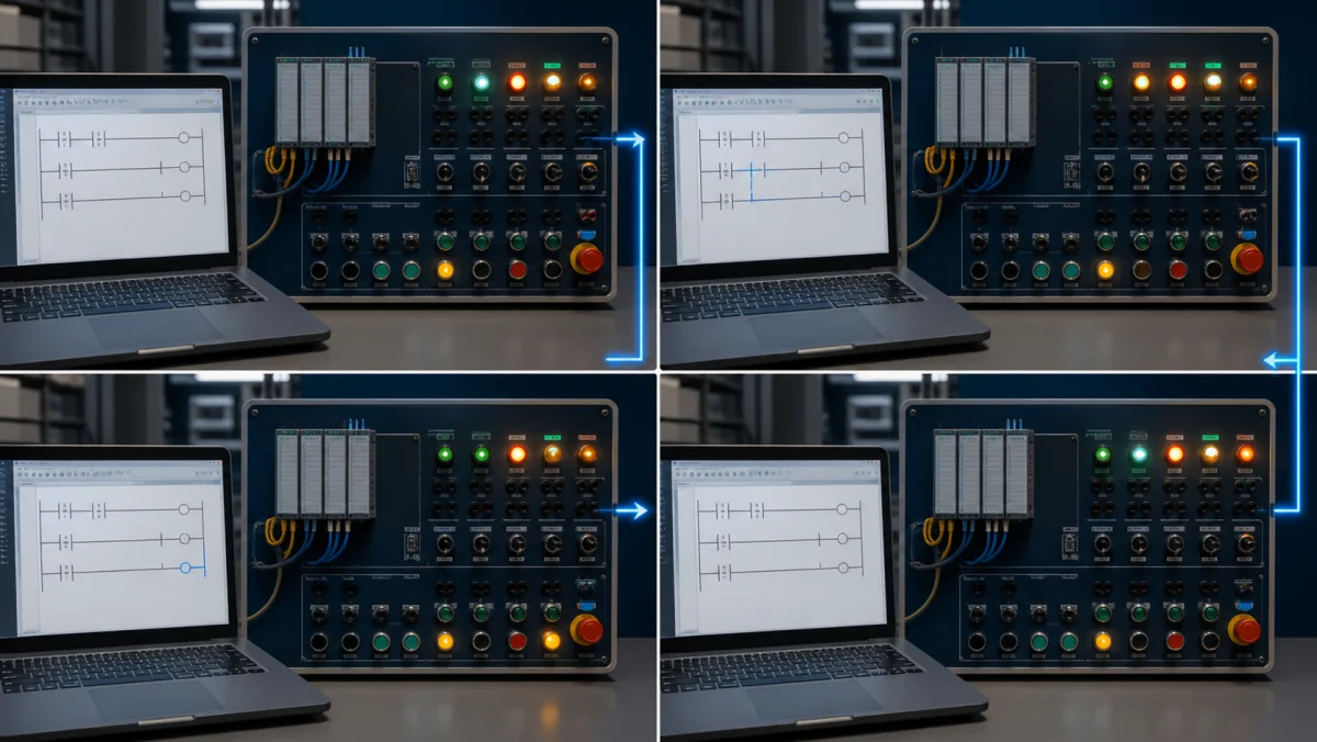
02Use the scan-cycle model to explain when input values are sampled, when logic executes and when physical outputs change.
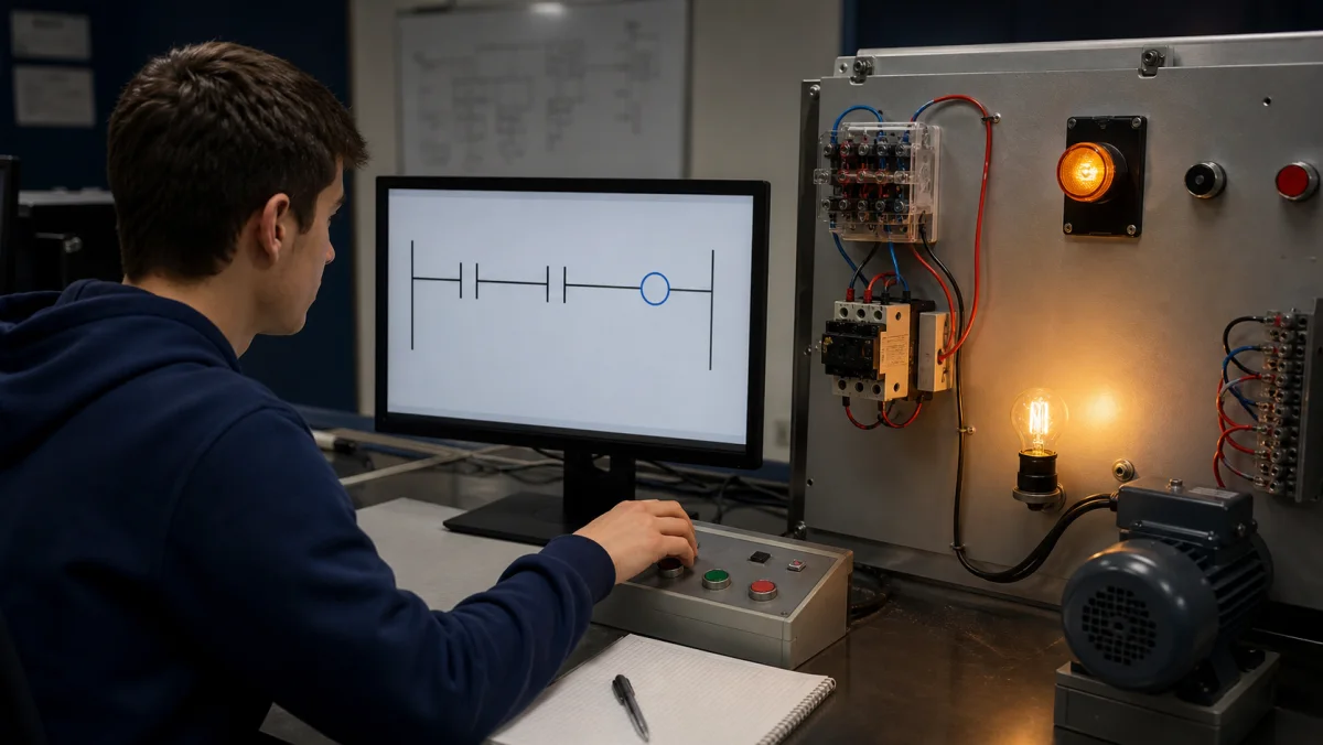
03A first program should produce an obvious physical result: one contact controls one coil and the learner can explain why it energizes.
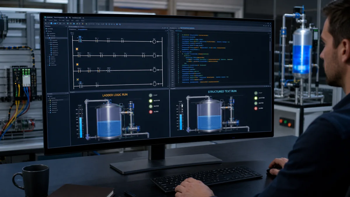
04Compare languages against the same machine behavior so the choice is about clarity and control requirements, not syntax alone.
05Progress from discrete cause and effect to timers, interlocks, sequencing, analog control and fault diagnosis in deliberate steps.
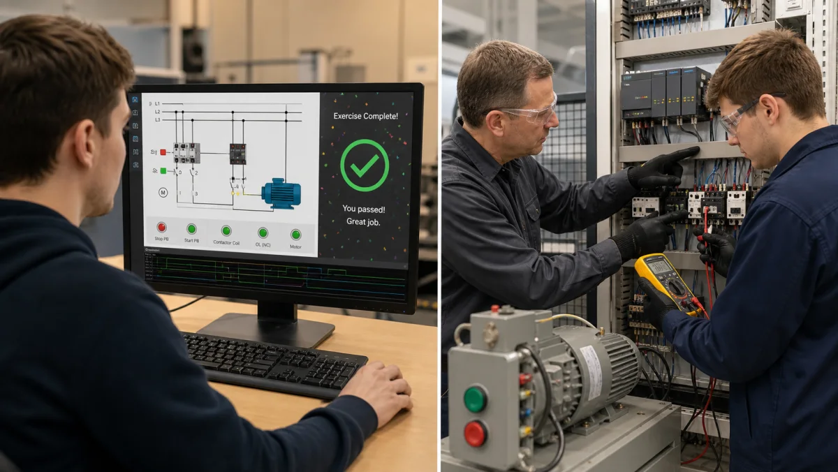
06Simulation builds repeatable logic and diagnosis skill; supervised hardware practice adds wiring, measurement, safety and commissioning judgment.
Overview
Who learns PLC programming, and why.
PLC programming is the craft of writing controller logic that runs on a programmable logic controller — the industrial computer that reads sensors and drives motors, valves, and conveyors in a factory, water treatment plant, or process line. If you have ever pressed a crosswalk button and watched the light cycle, tested a garage-door safety beam, or stood next to a bottling line, you have interacted with a PLC.
People come to PLC programming from three main directions. Electrical and mechatronics students pick it up as part of their degree and need practice beyond what the textbook and a two-hour lab session provide. Software engineers move into controls and automation roles and need to internalize a scan-based, I/O-driven programming model that is nothing like the web stack. Plant technicians already familiar with wiring relays step up to the logic side when their employer replaces hardwired panels with PLCs.
All three groups want the same thing: enough reps on real-feeling scenarios to develop intuition. That is what this page, and the ten scenarios linked below, set out to provide.
Planning range, not a promise. A focused learner may need roughly 15–20 hands-on hours to establish the basic contact, coil, timer, counter and latch model. Interlocks, sequences, analog control and troubleshooting require substantially more deliberate practice, while safe hardware commissioning requires supervised physical work.
The hardware you are learning to program: a CPU running your logic, connected to inputs (buttons, sensors) and outputs (motors, valves) through I/O modules.
Industrial PLC programming
How engineers program PLCs on a real project.
Writing rungs is only one step. Industrial PLC programming follows a repeatable workflow, and every step is something you can rehearse before you touch a live machine.
1. Read the functional description
Start from what the machine must do: normal sequence, stop conditions, interlocks, alarms and what happens after a fault or power loss. Ambiguity here becomes bugs later.
2. Build the I/O list and tag names
Map every pushbutton, sensor, contactor and valve to an input or output address and give it a meaningful tag name, such as StartPB or Conveyor1_Run.
3. Write the logic
Program the behavior in ladder logic, Structured Text or function blocks, usually organized into routines for modes, sequences, outputs and alarms.
4. Test offline or in simulation
Force inputs, step through normal, boundary and fault cases, and confirm each output does what the description says before any hardware moves.
5. Download and commission
Download to the controller, check every I/O point against the wiring, then prove the sequence on the machine under a supervised commissioning procedure.
6. Monitor, troubleshoot and maintain
Most PLC work after startup is reading live logic to find why a machine stopped. Clear, well-commented code is what makes that fast.
The path
How to learn PLC programming, in order.
Courses (RealPars, PLC Academy, Udemy) and YouTube playlists are good for theory. The piece they cannot give you is reps — writing logic, running it, watching it fail a test, and fixing it. This page is built around that loop. Here is the sequence that works.
Step 1 — Learn the model, not the buttons
Before any rung, understand the scan cycle and the I/O image table: a PLC reads inputs, runs your program top-to-bottom, then writes outputs, forever. Almost every beginner confusion (“why did my coil flicker?”) comes from not having this model. Five minutes on the diagrams below saves hours later.
Step 2 — Learn ladder logic first
Start with ladder logic — normally-open and normally-closed contacts, output coils, series (AND) and parallel (OR) branches. It is the most-used PLC language and it maps directly onto relay schematics, so it is the fastest to read. Write a one-rung program that turns a lamp on with a button. That is your first real PLC program.
Step 3 — Add the four building blocks
Layer on seal-in latching (hold a motor running off a momentary button), timers (TON / TOF / TP), counters (CTU / CTD), and edge detection (R_TRIG / F_TRIG). These four cover the large majority of real industrial logic. The Fundamentals section below explains each with a diagram.
Step 4 — Build on auto-graded scenarios
Move into the scenario library. Guided scenarios give you an I/O list, a written objective, and an objective test suite. You write the ladder, hit Run, and the grader tells you exactly which requirement failed. That feedback loop — not watching a video — is where the skill actually forms. A free account currently includes 32 source-tagged free-tier practice records; access can vary with account state and staged rollout.
Step 5 — Branch into Structured Text and a vendor
Once ladder feels natural, learn Structured Text for the math-heavy and looping logic that ladder makes awkward, and pick a target vendor — Allen-Bradley (Studio 5000) or Siemens (TIA Portal). The IEC 61131-3 standard means the concepts transfer; only the addressing and tooling change. When you are ready for a credential, see the structured course and certification guide.
The international standard. Learn ladder first, then Structured Text; the rest you can pick up by need.Structured Text reads like code. Reach for it once a sequence gets too tangled to draw as rungs.
Languages
PLC programming languages (IEC 61131-3).
The IEC 61131-3 standard defines the languages most controllers use. Vendors rename instructions and add their own libraries, but the language model transfers between brands. Learn ladder logic first, then Structured Text.
Language
Type
Best for
Ladder Diagram (LD)
Graphical
Discrete on/off control, interlocks and anything maintenance technicians must read at the machine.
Structured Text (ST)
Text
Math, data handling, loops, recipes and complex decisions that would take many rungs.
Function Block Diagram (FBD)
Graphical
Analog signal chains, PID loops and reusable blocks wired together like a signal-flow diagram.
Sequential Function Chart (SFC)
Graphical
Organizing step-by-step sequences such as batch phases or machine cycles into steps and transitions.
Instruction List (IL)
Text (legacy)
Reading older programs only. IL was deprecated in the 2013 edition of IEC 61131-3 and removed in the 2025 edition.
PLC coding
What PLC code looks like.
Here is the same motor start/stop program written two ways. A momentary Start button starts the motor, the motor's own bit holds it on (the seal-in), and Stop or an overload trip turns it off.
Ladder logic (text form)
|--[ Start ]--+--[/ Stop ]--[/ Overload ]--( Motor )--|
|             |
|--[ Motor ]--+
Structured Text (IEC 61131-3)
Motor := (Start OR Motor)
         AND NOT Stop
         AND NOT Overload;
Read the rung left to right: power flows through Start or the Motor holding contact, then through the normally closed Stop and Overload contacts, to the Motor coil. The Structured Text line is the same Boolean expression. Here Stop is true while the button is pressed; on real panels Stop buttons are usually wired normally closed, so the logic examines the healthy input as closed instead. Instruction names change by brand — Allen-Bradley writes these contacts as XIC and XIO — so the PLC codes reference maps the common mnemonics, and the PLC instruction list explains each one with a runnable example.
On the job you program PLCs in the manufacturer's software for that controller family. The concepts carry over; the menus, addressing and instruction names do not.
Studio 5000 Logix Designer
Rockwell Automation (Allen-Bradley)
ControlLogix and CompactLogix controllers; tag-based ladder logic with mnemonics such as XIC, XIO and OTE.
TIA Portal (STEP 7)
Siemens
S7-1200 and S7-1500 controllers; LAD, FBD, SCL (Structured Text) and GRAPH (sequences).
CODESYS
CODESYS Group
IEC 61131-3 development environment used by many hardware makers; a free download for learning.
GX Works
Mitsubishi Electric
MELSEC controllers; ladder logic with device addresses such as X, Y and M.
Vendor tools usually need a license and a Windows PC. This simulator is a browser-based practice environment for the logic, not a replacement for vendor software. See the free PLC programming software guide and the PLC software download guide when you are ready to install a vendor environment.
Fundamentals
The PLC programming fundamentals you need first.
Before scenario one, make sure these concepts click. Skip any you already know.
The scan cycle
A PLC runs a three-phase loop: read all inputs into an image table, execute the user program top-to-bottom, then write the output image back to physical outputs. Every rung you write is evaluated once per scan. Scan time is typically 1–50 ms on industrial hardware. Internalizing the scan model explains why coil order matters, why a rung can fire twice in one cycle, and why edge-detection exists.
The loop that runs forever while the PLC is powered. Your whole program is evaluated once per scan.
Rungs, contacts, and coils
Ladder logic draws a "rung" across two power rails. Left to right, you place contacts (inputs) and end with a coil (output). A normally-open contact (XIC in AB, --] [-- in standard notation) passes power when its tag is true. A normally-closed contact (XIO, --]/[--) passes when its tag is false. The coil at the end energizes when power flows all the way across.
The vocabulary of ladder logic. Learn to read these four symbols and you can read most rungs.A single rung is a Boolean expression: power must flow from the left rail to the right to energize the coil.
Latching (set / reset)
Most coils are non-retentive — they de-energize the instant the rung conditions fail. Latching solves the problem that most push-buttons are momentary. A SET / OTL coil turns the bit on and leaves it on; a RESET / OTU coil turns it off. The canonical three-wire motor seal-in rung uses a latch to keep a contactor energized after you release the START button.
The most-reused rung in PLC programming: the output seals itself in around a momentary START, with STOP and overload breaking the seal.
Timers
The TON (on-delay timer) starts counting when its input goes true and sets its .Q output when the accumulator reaches the preset. TOF (off-delay) does the opposite. TP (pulse) produces a fixed-duration output pulse on a rising edge. Every scenario on this site uses timers; the Traffic Light scenario is essentially a timer-driven state machine.
Timing diagram for a TON. The done (.Q) bit waits for the preset, then follows the input until it drops.
Counters
CTU (count up) increments on rising edges, fires its .Q when the accumulator reaches the preset, and resets on command. CTD counts down. CTUD does both. Counters show up in conveyor-sort logic, batch counts, and anywhere you need to track discrete events.
A CTU counts discrete events — parts off a conveyor, cycles complete — and trips its done bit at the preset.
Edge detection
R_TRIG fires for exactly one scan on a false-to-true transition; F_TRIG fires on true-to-false. Edge detection is how you make a rung respond to a push-button event rather than to the button being continuously held. Most beginner bugs in ladder logic are solved by adding an edge-detect block where you meant one.
The IO table
Every physical input and output is mapped to an address. In Allen-Bradley: I:0/0, O:0/0. In Siemens: %I0.0, %Q0.0. In IEC 61131-3: you declare a tagged variable at an address (START_PB AT %I0.0 : BOOL;). Every scenario on this site ships with its IO list printed in the scenario brief; your first job is to map it mentally before you write a rung.
Every rung references addresses like these. Mapping the I/O list to physical devices is step zero of every scenario.
Start without an account
Run your first PLC rung.
The guided first program uses one contact and one coil: flip a switch and watch the output light energize. It demonstrates the edit, run and observe loop without asking for an account or pretending to be a full vendor runtime.
After that first rung, create a free account to use the source-tagged free-tier scenarios in the full editor, save progress and run their automated checks. Catalog access depends on account state, tier, entitlement and staged rollout.
Animated preview: a timer-driven traffic-light sequence stepping through its phases while the scan counter climbs. The Traffic Light scenario asks you to write this logic yourself.
Each scenario introduces one or two new concepts and assumes everything before it. The source catalog spans 170 practice records across motor control, water/HVAC, packaging, safety, and process verticals; visible availability varies by account, plan, entitlement, and staged rollout. Resist the urge to skip fundamentals — early sequencer practice makes complex work tractable.
We will say this clearly: a simulator is not a replacement for real hardware experience. You will eventually want time on an actual controller — wiring inputs, dealing with sinking-vs-sourcing DC, watching a contactor physically pull in, debugging an analog sensor with a multimeter. The logic half of PLC programming transfers cleanly from simulator to hardware; the wiring and commissioning half does not.
What this simulator does is make logic iteration faster and safer. You can rerun sequences and fault states without risking a physical actuator, then take a more deliberate program into a supervised hardware lab. It complements rather than replaces electrical safety training and real commissioning practice.
Once the scenarios start to feel easy, add supervised practice on an appropriate training controller, protected low-voltage I/O and field devices, following the manufacturer documentation and your site safety procedures. A vendor or controls credential can document formal study, but employers will still judge troubleshooting, safety and practical reasoning.
Realistic timeline
How long does it take to learn PLC programming?
A rough planning range for contacts, coils, timers, counters and latching is 15–20 focused hands-on hours, but prior electrical knowledge, practice quality and the target role can move that number substantially. Interlocks, sequencing, analog control and troubleshooting require additional deliberate practice. Available practice records are auto-graded against scripted test cases, so every hour of practice includes feedback a video course cannot give.
When you need depth alongside the reps, the same platform includes written guides, wiring and fault-finding practice, and interactive sensor learning materials built on IEC 61131-3 languages. The payoff is measurable: O*NET (U.S. Department of Labor) reports 2025 median wages of $63,190 for electricians and $64,520 for industrial machinery mechanics, with roughly 81,000 and 45,700 projected US job openings a year respectively through 2034. Those occupations are broader than PLC programming, so treat the data as labor-market context rather than a salary or placement promise.
“Reading about seal-in rungs is like reading about swimming. Write the rung, watch the grader fail it on a timing edge, fix it — that ten-minute loop teaches more than any chapter, and it is the only reason this simulator exists.”
Questions
Frequently asked.
PLC programming is writing the control logic that a programmable logic controller runs to operate a machine or process. The program reads inputs such as pushbuttons and sensors, applies logic, timers and counters, and switches outputs such as motors and valves on every scan. Most PLCs are programmed in ladder logic or Structured Text, the IEC 61131-3 languages.
Ready to start?
Build and run the guided Switch & Light program without an account, then save your progress and continue through the free learning path.