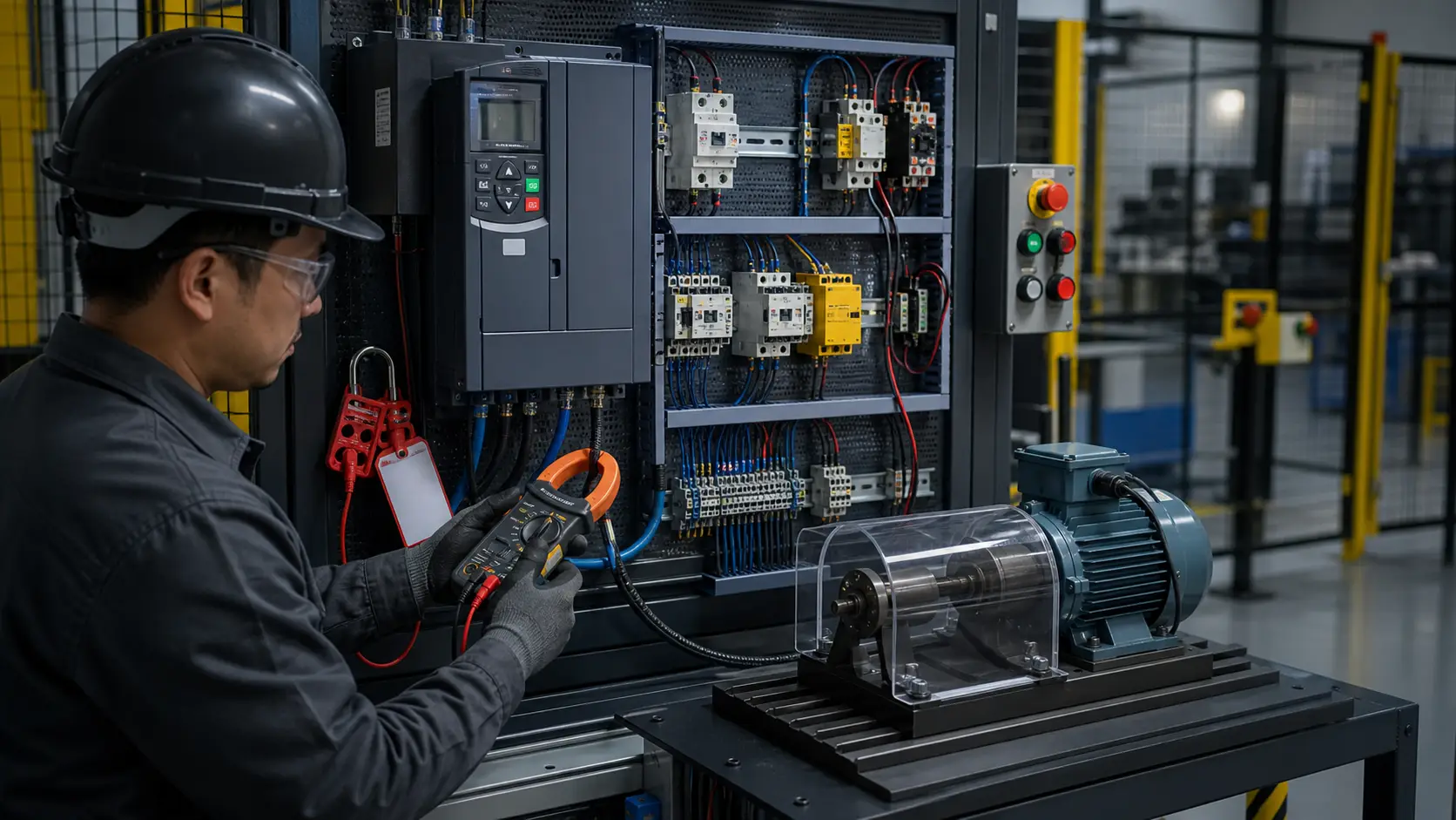
What you'll learn
A **Variable Frequency Drive (VFD)** controls motor speed by converting fixed-frequency AC mains to variable-frequency AC output. The core insight you must take away from this lab:
Lab time: ~18 minutes.
Lesson briefing
VFD Run/Stop with PLC Digital Command
A Variable Frequency Drive (VFD) controls motor speed by converting fixed-frequency AC mains to variable-frequency AC output. The core insight you must take away from this lab:
The PLC does NOT switch motor power. The VFD does.
The PLC issues a low-voltage (24 V DC) signal on its digital output. The VFD's internal power stage uses that signal as a command to close (or open) the high-power path to the motor.
Three circuits in one panel
1. Power circuit AC supply enters the VFD on terminals L1, L2 (L3 on three-phase drives). The VFD's rectifier-inverter converts this to variable AC and outputs it on terminals U, V, W. These connect directly to the motor windings (T1, T2, T3). No contactor, no relay, no switch sits between VFD and motor in a direct-on-line VFD installation.
2. Control circuit The PLC output (Y0) connects through a terminal block to the VFD's STF terminal (start-forward). The VFD's SD terminal is the DC common reference (0 V). When Y0 energises (closes the STF–SD loop), the VFD ramps up to the programmed speed setpoint. When Y0 de-energises, the VFD decelerates to stop.
3. PE/ground bonds All metalwork — PSU chassis, VFD chassis, motor frame — ties to a common ground bar (PE). This limits touch voltage in a fault condition.
What to wire
- Seed the +24 V and 0 V distribution buses from the PSU outputs.
- Power the PLC from the +24 V and 0 V buses.
- Connect PSU AC terminals (L, N) to VFD power input (L1, L2).
- Wire the power circuit: VFD U → motor T1; VFD V → motor T2; VFD W → motor T3.
- Control circuit: PLC Y0 → tb-ctrl.t0; tb-ctrl.t1 → VFD STF; 0 V bus → VFD SD.
- PE bonds: PSU PE, VFD PE, motor PE → ground bar slots pe0/pe1/pe2.
Hints
Start with power distribution: psu-1.+V → tb-24v.t0 and psu-1.0V → tb-0v.t0. These seed the two DC distribution buses.
Sign up to unlock the full hint sequence.
Sign up to unlock the full hint sequence.
Sign up to unlock the full hint sequence.
Sign up to unlock the full hint sequence.
Sign up to unlock the full hint sequence.
This lesson uses 9 placed components on the lab canvas. Components are vendor-neutral (no proprietary trademarks); the wiring rules apply to any equivalent industrial part.
Sign up to preview
Create a free account to preview this Pro lab; upgrade to open the interactive circuit.
Sign up to preview →